My son got one of these Leap Frog toys a few years ago as a gift. He enjoys playing with it very much. I am not sure how much counting and learning he is doing but it makes funny noises and sings to him so its a lot of fun.
Recently the unthinkable happened. It died. Not the batteries but something else. I took the back off to look at what might be wrong (which was very easy for a toy). Unfortunately, other than the speaker, a switch, battery compartment, and a ribbon cable to the front, there wasn’t much to investigate. A couple of glop tops and nothing else. I fiddled a bit more with it but everything “external” seemed fine.
Did I mention my son really loves this toy?
It can’t be that hard to make something similar using the carcass of the old one, right? It has all the external bits and pieces. I just need to figure out how to take some input and play some sounds. Right? So I spent a few hours figuring out the basics of what I wanted to change this thing into. Audio driven from an atmega328. A simple amplifier. Make it power friendly (and run off of two AA batteries).
But what about that input? The original toy had a very thin membrane keyboard basically. I need a membrane keyboard of my own. There are a few places that will make custom membrane keypads but that is too costly. You can buy one of these hobbyist keypads cheaply ($3-$10 from Amazon and less than that from places like DXSoul).
That screams fun right?
What other options are there?
I decided to make my own. There are a few tutorials on building membrane keypads. Most of the DIY keypads I’ve found don’t seem like they would be all that reliable nor resilient. I’m not looking for something to last forever but it should last long enough to warrant the 30 minutes of work needed to make it.
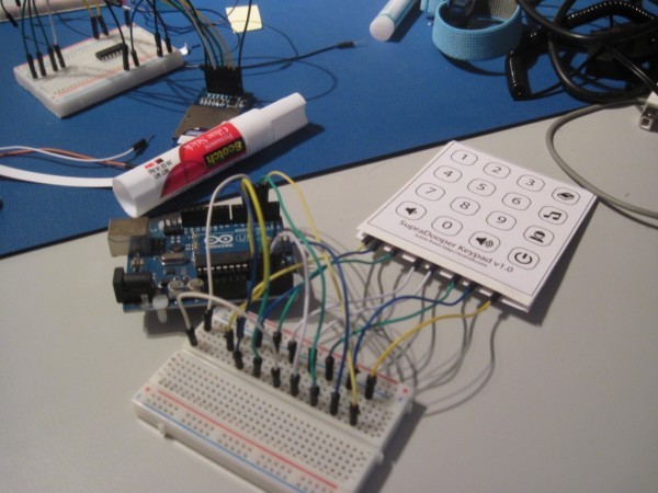
Future blog posts will cover more details of the final new “front panel” of the toy. The rest of this post will cover a (boring) prototype I used to verify some thinking.
As mentioned earlier, there are sites out there that provide details of what a membrane keypad is and (more generally) what a matrix keypad is. For my version, I’ll end up with four layers:
- A “front decal” layer that has the images of the buttons. This is what the user sees.
- A “top foil” layer that contains the traces that link the rows of buttons together and provides “pads” onto which to connect wires. The top foil layer is the opposite side of the front decal layer (i.e. the “inside” of the front of the keypad).
- A “bottom foil” layer that contains the traces that link the columns of buttons together and provides pads. The bottom foil layer is the “inside” of the back of the keypad.
- A “cutout” layer. This layer is sandwiched between the top and bottom foil layers and provides just enough separation to prevent the row and column traces from shorting when a button is not pressed.
For more detail: Make a Custom Membrane Keypad for Arduino