Summary of Make an Arduino LCD shield
This tutorial guides users in building a custom Arduino LCD shield using a protoshield, an HD44780-compatible LCD module, and a trimpot for contrast. The process involves testing components on a breadboard, creating a schematic, and soldering the circuit permanently while considering existing shield features like LEDs or switches.
Parts used in the Arduino LCD Shield:
- HD44780-compatible LCD module (backlit or non-backlit)
- 10k linear trimpot
- Blank protoshield matching the Arduino board
- Various header pins
- Paper for drawing schematics
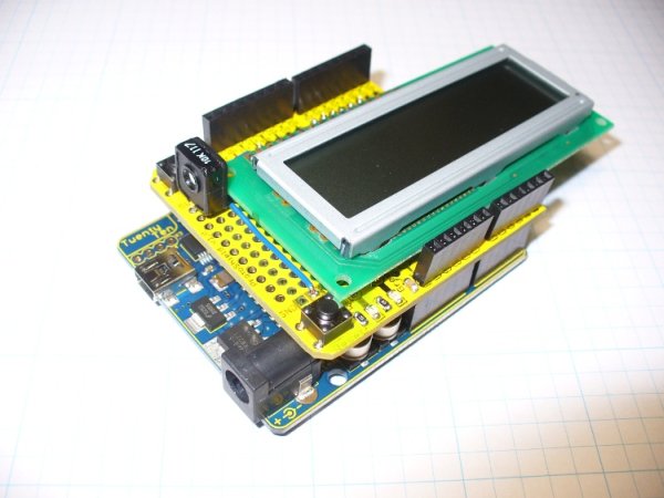
In this short tutorial we make an Arduino LCD shield.
Updated 18/03/2013
Today we are going to make an Arduino shield with an LCD module. More often than not I have needed to use an LCD shield in one of my projects, or with the Arduino tutorials. Naturally you can buy a pre-made one, however doing your own is always fun and nice way to pass an afternoon. Before we start, let me say this: “to fail to plan is to plan to fail”. That saying is very appropriate when it comes to making your own shields.
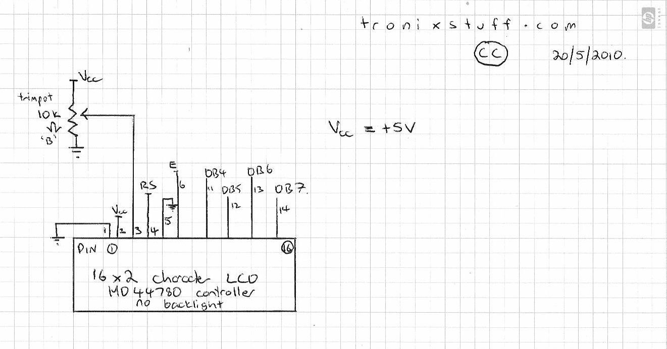
Next, test your parts to ensure everything works. So, draw a schematic so you have something to follow:
And then build the circuit on a solderless breadboard, so you can iron out all the hardware bugs before permanently soldering into the shield. If you have a backlit LCD, pins 15 and 16 are also used, 15 for backlight supply voltage (check your data sheet!) and 16 for backlight ground:
Once connected, test the shield with a simple sketch – for example the “HelloWorld” example in the Arduino IDE. Make sure you have the library initialization line:
LiquidCrystal lcd();
filled with the appropriate parameters. If you’re not sure about this, visit the LCD display tutorial in my Arduino tutorials.
Now to make the transition from temporary to permanent. Place your components onto the protoshield, and get a feel for how they can sit together. Whilst doing this, take into account that you will have to solder some jumper wires between the various pads and the digital pin contacts and the 5V strip at the top row, as well as the GND strip on the bottom row. You may find that you have to solder jumper wires on the bottom of the shield – that’s fine, but you need to ensure that they won’t interfere with the surface of your Arduino board as well.
Furthermore, some protoshields have extra functions already added to the board. For example, the shield I am using has two LEDs and a switch, so I will need to consider wiring them up as well – if something is there, you shouldn’t waste the opportunity to not use them.
If your shield has a solder mask on the rear, a great way to plan your wiring is to just draw them out with a whiteboard marker:
- an LCD module (backlit if possible, but I’m being cheap and using a non-backlit module) that is HD44780-compatible
- a 10k linear trimpot, used to adjust the LCD contrast
- a blank protoshield that matches your Arduino board
- various header pins required to solder into the shield (they should be included with your protoshield)
- plenty of paper to draw on
For more detail: Make an Arduino LCD shield
- Why should I plan before making my own shield?
The article states that failing to plan is planning to fail, which is crucial when designing shields. - How do I test parts before permanent soldering?
You should draw a schematic and build the circuit on a solderless breadboard to fix hardware bugs first. - Which pins are used if the LCD has a backlight?
Pins 15 and 16 are used for backlight supply voltage and backlight ground respectively. - What library initialization line is required for the sketch?
The code must include LiquidCrystal lcd() filled with appropriate parameters. - Where might I need to solder jumper wires?
Jumper wires may be needed between pads, digital pin contacts, the 5V strip, and the GND strip. - Can I solder jumper wires on the bottom of the shield?
Yes, but you must ensure they will not interfere with the surface of your Arduino board. - Should I use extra functions already on the protoshield?
You should consider wiring them up if the shield has extra features like LEDs or a switch. - What is a good way to plan wiring on a shield with a solder mask?
Draw the wiring out with a whiteboard marker on the rear of the shield.