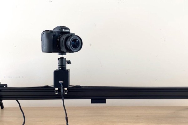
Summary of Make a Motorised Pan and Rotate Camera Slider
This article details the construction of a motorized pan and rotate camera slider using 2040 aluminum extrusions, Nema 17 stepper motors, and an Arduino Pro Mini. The build includes 3D-printed components for housing and mounting, driven by TMC2208 drivers and controlled via an OLED display and rotary encoder. The project involves mechanical assembly, custom PCB design, and complex programming to achieve smooth object tracking.
Parts used in the Motorised Pan and Rotate Camera Slider:
- Creality Ender 3 Pro 3D Printer
- 2040 Aluminium Extrusion 700mm
- 2040 V-Slot Gantry
- GT2 Tensioner
- GT2 5mm Pulley
- GT2 Belt
- Nema 17 2.5 Stepper Motors
- Camera Ball Joint Mount
- M5 T Slot Nuts
- M5 Machine Screws
- Arduino Pro Mini 5V
- TMC2208 Stepper Motor Drivers
- 100uF Capacitors
- 128x64 I2C OLED Display
- Rotary Pushbutton
- Header Pins
- Slider Switch
- M4 T Slot Nuts
- M4 Machine Screws
- PLA Filament
- PCB Way PCBs
- 5.5mm Barrel Socket
Supplies
The parts list for this build is quite lengthy, but a lot of these components you may having lying around if you do have an old 3D printer.
The 3D printer I’ve used to print some of the plastic components and housings is a Creality Ender 3 Pro.
Links from Amazon (Affiliate)
2040 Aluminium Extrusion 700mm – https://amzn.to/39XxadP
2040 V-Slot Gantry – https://amzn.to/3sORpCM
GT2 Tensioner – https://amzn.to/2XZWJVZ
GT2 5mm Pulley – https://amzn.to/3c7dua5
GT2 Belt – https://amzn.to/39RARBI
2 x Nema 17 2.5” Stepper Motors – https://amzn.to/2MaESsD
Camera Ball Joint Mount – https://amzn.to/364gO1H
M5 T Slot Nuts – https://amzn.to/2Ni4GDE
M5 Machine Screws – https://amzn.to/2AtFG5W
Arduino Pro Mini 5V – https://amzn.to/3qEhdQg
2 x TMC2208 Stepper Motor Drivers – https://amzn.to/3sLm7wC
2 x 100uF Capacitors – https://amzn.to/2UzqNqj
128×64 I2C OLED Display – https://amzn.to/3neur41
Rotary Pushbutton – https://amzn.to/3e2j8aY
Header Pins – https://amzn.to/2wY3k9g
Slider Switch – https://amzn.to/2Dqvn4c
Links from Banggood (Affiliate)
2040 Aluminium Extrusion 700mm – https://www.banggood.com/custlink/3v3dSFoqEt
2040 Gantry – https://www.banggood.com/custlink/mK3R9PaUEi
GT2 Tensioner – https://www.banggood.com/custlink/K3GhI5a2Ea
GT2 5mm Pulley – https://www.banggood.com/custlink/m3DYi5lMd0
GT2 Belt – https://www.banggood.com/custlink/GDKdItOzhN
2 x Nema 17 2.5” Stepper Motors – https://www.banggood.com/custlink/K3vhiPoMdM
Camera Ball Joint Mount – https://www.banggood.com/custlink/DKGdiVLMR7
M4 T Slot Nuts – https://www.banggood.com/custlink/DvDyIVoqrm
M4 Machine Screws – https://www.banggood.com/custlink/v3DY9toMJh
Arduino Pro Mini 5V – https://www.banggood.com/custlink/GGvYiFlkCC
2 x TMC2208 Stepper Motor Drivers – https://www.banggood.com/custlink/333EZVLzp5
2 x 100uF Capacitors – https://www.banggood.com/custlink/DKDdIPakc9
128×64 I2C OLED Display – https://www.banggood.com/custlink/mKDdStLkco
Rotary Pushbutton – Not Available
Header Pins – https://www.banggood.com/custlink/mvGhSHLqJ6
Slider Switch – https://www.banggood.com/custlink/vvmR9HoMrN
Step 1: Using Aluminium T-Slot Extrusions
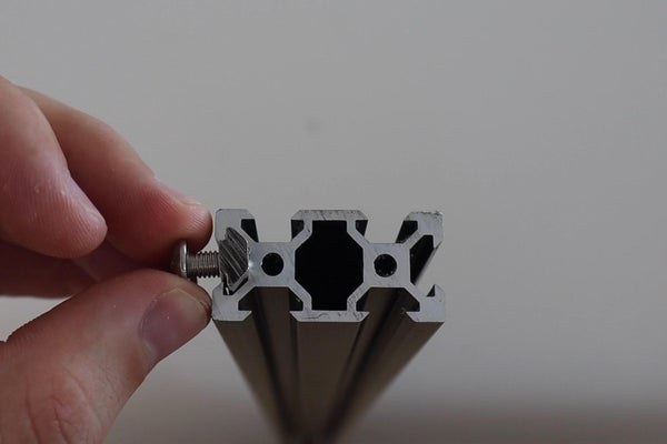
One of the easiest ways to build sliding rigs is to use these aluminium t-slot extrusions. They’re widely used in hobby CNC machines like 3D printers and laser cutters, so there are loads of accessories available for them and they’re relatively inexpensive.
Very simply, the shape of the extrusion is such that specially design nuts fit into the slots to secure brackets and accessories, and platforms or gantries are also able to slider over them.
I picked out a 2040 extrusion for my slider, along with a basic mount for a stepper motor, a sliding gantry, a belt tensioner and then the belt and pulley. I also got a ball joint camera mount so that the angle of the camera could be adjusted when it’s mounted to the slider.
You could also just use the aluminium extrusion and gantry to build a really cheap camera slider that is not motorised.
Step 2: Mount the Pan Motor
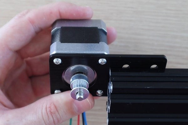
I mounted the pan motor to one end of the aluminium extrusion, with the motor shaft positioned in the middle of the upper slots. The motor bracket is held in place using some M5 button head screws and some M5 t-slot nuts.
I also installed the pulley onto the motor with the belt groove centred with the t-slot.
Step 3: Assemble and Mount the Rotate Motor
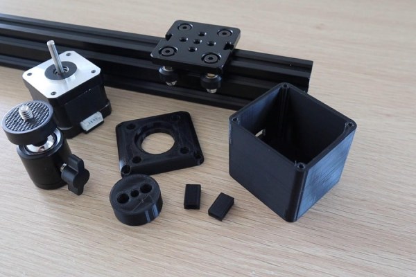
I then designed and 3D printed the rotation motor components. These components house the rotation motor and secure it to the gantry as well as mount the ball joint onto the end of the motor shaft. The 3D print files can be downloaded from the blog post.
Screw the stepper motor onto the housing’s cover plate. Then mount the bottom of the housing onto the gantry with some M5 screws and then put the motor into the housing and hold it in place with some more M3 screws.
The ball joint is mounted onto the adaptor using some M4 screws and is then pushed onto the motor shaft and held in place with an M3 screw.
You should then have a complete rotation motor assembly which will slide smoothly along the extrusion.
Step 4: Add Some Legs to Stand the Slider On
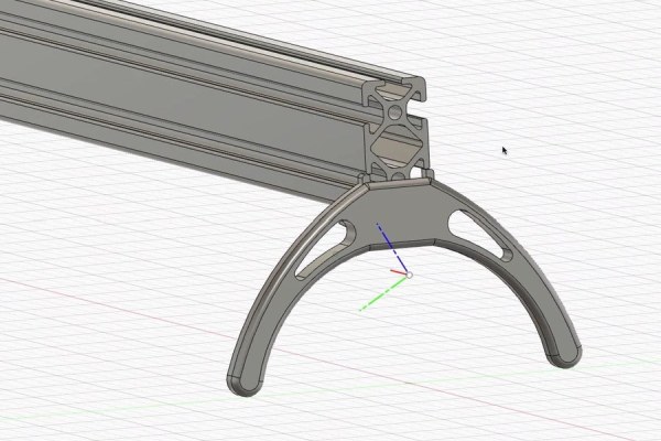
I then designed some legs for the camera slider to stand on. These were also 3D printed in black PLA. You can download the 3D print files from the blog post.
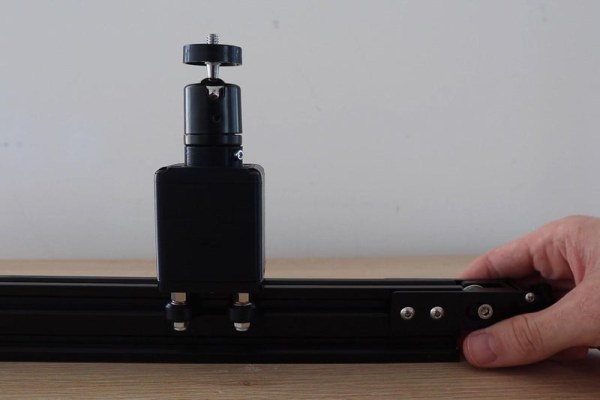
I also wanted the slider to be able to be mounted onto a tripod so that it could be better positioned and angled around my workspace. For this I designed and 3D printed a replica of the camera shoe which came with my tripod with two holes in it to bolt onto the gantry.
Install one leg on the motor side of the extrusion, then the tripod shoe in the middle and then finally the leg on the other side of the extrusion. These were all secured with M5 button head screws and t-slot nuts.
Step 5: Add the Belt and Tensioner
To finish off the mechanical assembly, we just need to add the belt.
The belt is held in place by wrapping one end around the gantry so that it overlaps itself and then clamping it together with one of the 3D printed clamps. The belt then goes around the motor pulley, through the middle of the extrusion, around the tensioner and connects to the other side of the gantry, again with a 3D printed clamp to hold it in place. The belt should be trimmed so that there is about 3cm of overlap on each side of the gantry.
You can then tension the belt by screwing in the tensioning nut on the end of the slider.
Step 6: Test the Electronic Components
Now that we’ve got the mechanical components assembled, we can get started with getting the motors moving.
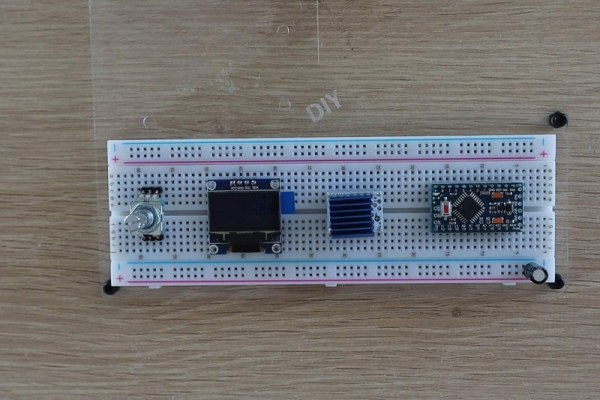
To drive the motors, I used two TMC2208 stepper motor drivers, which are controlled by an Arduino Pro Mini. I also added an OLED display and a rotary pushbutton encoder to select modes and input parameters.
I started out by connecting the main components together on a breadboard to check that they all worked correctly and that I had made the correct connections to the Arduino. I didn’t test both stepper motor drivers as the interface to the Arduino would be the same.
Step 7: Design and Assemble the PCB
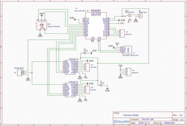
I drew up a schematic and designed a PCB to mount the components onto. You don’t have to use a PCB, you can leave the components on a breadboard, but a PCB just makes a stronger and more reliable build, especially for something that you’ll be moving around a lot.
I got these PCBs made up by PCB Way, you can download the Gerber files from the blog post.
I then soldered the components onto the PCB, using header pin sockets for the Arduino and the OLED display. I used header pin sockets for the OLED display as I wanted to mount the display onto the lid of the case and run a short cable to the PCB.
Step 8: Make a Housing for the Electronics
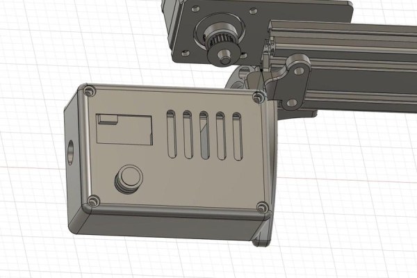
I then sketched the PCB into my CAD model and designed a plastic case to house it and to mount onto the slider rail.
I installed the PCB in the case, holding it in place with some M3 screws. I also made up a short power lead which fed from a 5.5mm barrel socket on the side of the case to the two power input pins on the PCB.
I put a switch onto the PCB to use if you’d like to, but I prefer to just have it on when it’s plugged in and off when it’s not. If you’d like to use the switch then you’ll need to modify the case to have a cutout near the switch so that you can access it. The switch is useful if you’re running the slider on batteries or if you’ve got it permanently set up somewhere.
Step 9: Program the Arduino
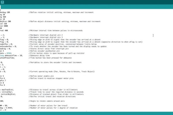
With all that done, it’s time to program the Arduino, which was more of a task than I had anticipated.
Making menus with the rotary pushbutton encoder is a great way to input information with a single device, but you do land up having to do quite a lot of programming to make up for it.
I got the simple pan and rotate functions working quite quickly and then got started on the object tracking mode.
I rather stupidly assumed that this was easy. You move the camera from A to B and rotate it at the same time by around 120 degrees. So I’d just divide up the pan and rotate movements and it would work perfectly.
Except that that’s not how it works at all.
In order to keep the camera fixed on an object, you need to rotate the camera slowly in the beginning, quicker in the middle and slower at the end again. There’s a bit of trigonometry involved, but I got it working eventually.
Step 10: Finish It Off
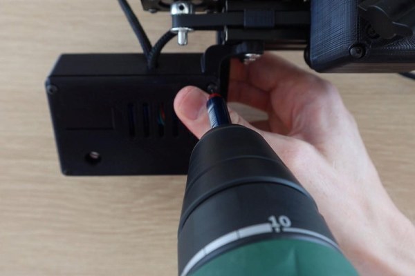
To finish off the slider, I closed up the electronics case with some M3 screws and put the stepper motor wiring into some sleeving to keep it neat.
Source: Make a Motorised Pan and Rotate Camera Slider
- How do you secure brackets to the aluminium extrusions?
Specially designed nuts fit into the slots to secure brackets and accessories. - Can you build this slider without motorization?
Yes, you can use just the aluminium extrusion and gantry to build a cheap non-motorised camera slider. - What is the best way to input parameters on the device?
A rotary pushbutton encoder is used to select modes and input information via menus. - Does the belt need specific tensioning?
The belt is tensioned by screwing in the tensioning nut on the end of the slider. - Why was a PCB chosen over a breadboard?
A PCB makes the build stronger and more reliable, especially for something that will be moved around. - How do you keep the camera fixed on an object during movement?
You must rotate the camera slowly at the beginning, quicker in the middle, and slower at the end. - Is a switch required for power management?
A switch is optional; the author prefers leaving it on when plugged in and off when not. - What material was used for the 3D printed legs?
The legs were 3D printed in black PLA.