
Summary of Make A G Meter using Arduino
Summary: The author converted five unused dash LED positions in a late-80s VW into a lateral G-meter using an ADXL335 accelerometer and RGB LEDs controlled by either an Arduino or a standalone ATmega168/328 circuit. The project maps the ADXL335 X-axis output to LED drivers (common anode in the example), with resistors and power regulation to run on 3.3V from a 9V source. Wiring details, pin assignments, and notes about inverted logic for common anode LEDs are provided.
Parts used in the G Meter:
- Arduino (optional)
- 5 RGB LEDs (common anode in example)
- Project box (optional)
- 9V battery
- ADXL335 accelerometer (from Adafruit)
- Perf board
- 5 resistors 1K ohm
- 5 resistors 500 ohm
- Small jumper wires
- Circuit board (for standalone)
- ATmega168 or ATmega328 (for standalone)
- 28 pin socket
- 16 MHz resonator
- 104 capacitor
- 10 uF capacitor
- 3.3V regulator LM1117T
- Ribbon cable
- Header connectors
- 9V battery connector
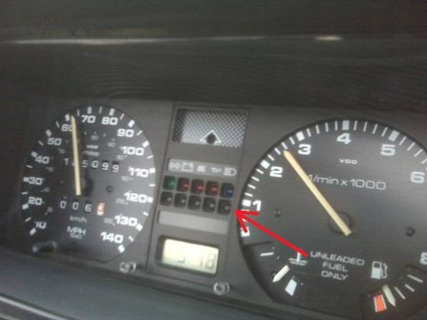
I have a late 80’s VW and the gauge cluster has 5 dummy LED locations underneath the other warning lights. Well I was tired of the m not doing anything, so I decided to do something about it. I came up with the idea to put a lateral gravitational force mater (G Meter) in there place
Step 1:
Gather up the needed supplies
If you wish to use your Arduino:
1- Arduino
5- RedGrenBlue LEDs (Mine are common anode)
1- Project box (if you don’t want it in your dash)
1- 9v Battery
1- Accelerometer (I used ADXL 335 from Adafruit) http://www.adafruit.com/products/163
1- piece of Perf board
5- Resistors 1K ohm
5- Resistors 500 ohm
And some small wires for jumpers.
All parts needed if you wish to make it standalone:
1 -Circuit Board
1- ATmega168/328
1- 28 Pin socket
5- RGB LEDs (Mine were common anode)
5-Resistors 1K ohm
5-Resistors 500 ohm
1- 16MHZ Resonator
1- 104 cap
1- 10uf cap
1- 3.3v rg. (LM1117T)
1- ribbon cable
1- header connectors
1- Acceleromoter
1- 9v Batt. Connector
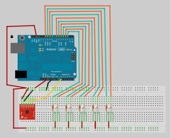
Here is the picture of the wiring needed for a breadboard setup.
The orange wires hook to the 500 ohm resistors and then hook to the RED LED cathode.
The Green wires hook to 1kohm resistor the hook to the GREEN LED cathode.
The common anode is hooked to +3.3v
X axis output of ADXL335 goes to PIN 0 (Picture is slightly different)
+3.3v and Gnd are hooked to power and ground pins of ADXL335
The AREF pin on the Arduino is hooked to +3.3v
Step 2:
If you use common cathode you will need to change the code.If you wish to change the pin number just change the beginning of the code:int led1G = 2;
int led1R = 3;
int led2G = 4;
int led2R = 5;
int led3G = 6;
int led3R = 7;
int led4G = 8;
int led4R = 9;
int led5G = 10;
int led5R = 11;
int X_AXIS = 0;
- What sensors are used to measure lateral G?
The ADXL335 accelerometer is used for the X axis measurement. - Can I use my Arduino for this project?
Yes, the project can be built using an Arduino or as a standalone ATmega168/328 circuit. - Does the example use common anode or common cathode LEDs?
The example uses common anode RGB LEDs. - How is the ADXL335 powered in the example?
The ADXL335 is powered from +3.3V and ground. - Which Arduino pin reads the X axis output?
The X axis output of the ADXL335 is connected to analog PIN 0. - What must be done differently for common anode LEDs regarding digitalWrite?
With common anode LEDs digitalWrite(pin, HIGH) turns the LED off, so logic is inverted compared to common cathode. - What resistors are used for the LED color channels?
The wiring uses 500 ohm resistors for the red cathodes and 1K ohm resistors for the green cathodes in the example. - What voltage is the Arduino AREF connected to?
The AREF pin on the Arduino is hooked to +3.3V in the example.
