This Instructable will show you an easy way to wire up an Arduino Nano to various PCB breakout boards. This project came about during my search for an effective, but non-destructive way to interconnect several module.
I had five modules I wanted to interconnect:
- An Arduino
- A 5-inch 800×480 graphical LCD touch panel from Haoyu electronics
- An SD card reader
- A DS1302 real-time clock unit
- A MAX485 RS-485/RS-422 transceiver
The touch panel and the real-time clock modules had previously been used in my my Dali Clock and my Rainbow Synthesizer projects, but those prototypes had been done on a breadboard and had been dismantled to make space for new projects.
It became clear to me that having these all these modules together in a permanent fixture would allow me to spend more time writing software and less time wiring things up on a breadboard. At the same time, I did not want to permanently solder anything together so I could preserve the modules for future use.
This Instructable shows how I put it all together using wire wrapping.
Step 1: Planning the Interconnections
My first step was to map out how to interconnect all the modules to the available pins on an Arduino Nano. The display and the SD card are both SPI modules. SPI is a bus, so the CLK, MISO and MOSI lines can be daisy chained to the modules that need it along with power. Each would require their own CS (Chip Select) pin, however.
I decided to put the RTC module on its own pins because earlier experiments had shown me it wasn’t quite SPI compatible. The transceiver modules also needed their own pins.
After mapping everything out, I found it looked like this:
- Arduino Pin GND -> LCD GND -> SD Card GND -> Transceiver GND -> RTC 5V
- Arduino Pin 5V -> LCD 5V -> SD Card 5V -> Transceiver VCC -> RTC VCC
- Arduino Pin 13 -> LCD CLK -> SD Card CLK
- Arduino Pin 12 -> LCD MISO -> SD Card MISO
- Arduino Pin 11 -> LCD MOSI -> SD Card MOSI
- Arduino Pin 10 -> LCD CS
- Arduino Pin 9 -> LCD PD
- Arduino Pin 2 -> LCD INT
- Arduino Pin 8 -> RTC CLK
- Arduino Pin 7 -> RTC DAT
- Arduino Pin 6 -> RTC RST
- Arduino Pin 4 -> SD Card CS
- Arduino Pin 14 -> Transceiver DI
- Arduino Pin 15 -> Transceiver DE
- Arduino Pin 16 -> Transceiver RE
- Arduino Pin 17 -> Transceiver RO
Pins 0 and 1 are used by the USB interface, so they were off-limits. Digital pins 3, 5, 18 and 19 remained free, as did analog inputs A4 through A7, allowing for future expansion.
Step 2: The Problem With Jumper Wires and Wirewrap As a Solution
Initially I had attempted to interconnect everything with short custom crimped Y cables. However the crimps and connectors are only designed to take one wire at a time. Cramming multiple wires in one housing was difficult and led to fragile joints that didn’t last long. Not only was the crimping process time consuming, once in use the connectors were likely to work themselves loose from pins, leading to additional wasted time tracking down intermittent faults.
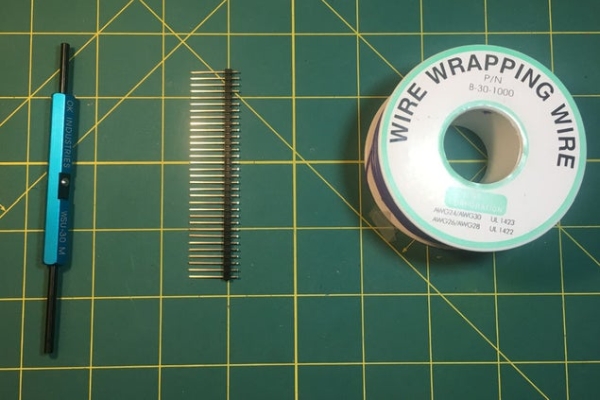
I had always wanted to give wire wrapping a try, so I thought this was a good opportunity to do so. After some research, I purchased a WSU-30 M tool, some extra long 19mm long single row headers and 30 AWG wire wrapping wire on eBay.
As a technology, wire wrapping has a long history. It was a popular way to make digital computers in the 60s, 70s and 80s and saw frequent use in telephone central offices. Although it was obsoleted by mass produced printed circuit boards, wire wrapping has the following advantages for the hobbyist:
- It is inexpensive and quick
- It is easy to apply and can be removed cleanly
- It works with the pin headers that are soldered to many breakout boards
- It forms a long lasting and reliable connection
- It allows multiple connections to and from each point (when long headers are used)
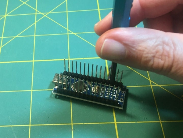
Step 3: Preparing an Arduino Nano
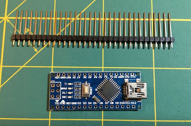
The next step was preparing my Arduino Nano. I had an Arduino Nano without any headers, which turned out to be handy, since I wanted to solder the extra long header pins to the top side so I could see the labels while wire wrapping.
I also soldered some extra long headers to the tiny breakout board that came with my display panel.
On the transceiver module, the screw terminals were on the opposite side of the headers, so I desoldered them and moved them to the same side as the headers.
The other boards had short headers already soldered on in the correct side, so I kept them as is.
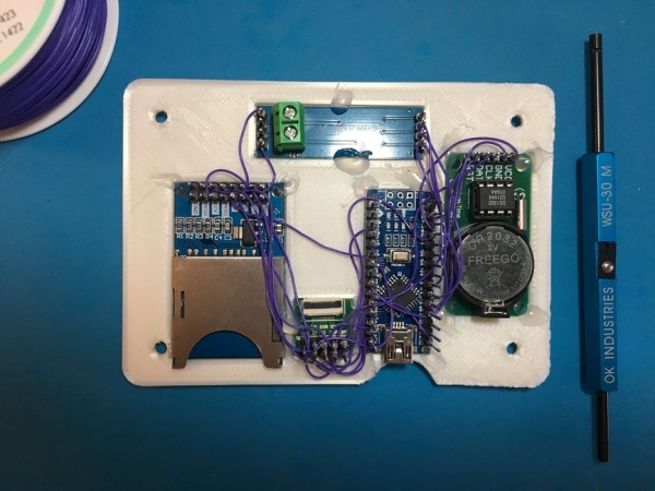
Step 4: Designing a Tray
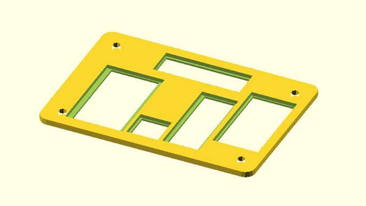
I wanted to be able to mount all the electronics in the back of the LCD stand I had created for my Dali Clock instructable, so I modeled up something in OpenSCAD. I made cutouts for the various boards I wanted to mount.
After I printed out the tray, I hot-glued all the modules in place.
Step 5: The Process of Wirewrapping
The process of wire wrapping consists of the four steps: measuring, cutting, stripping, and wrapping.
I measure out enough wire for spanning the two points I want to connect, plus an additional inch on each end for wrapping. Then, I strip off 1 inch of insulation on each end and use the tool to wrap the wire onto the post.
The following is the exact technique I use, which you can see on my demonstration video:
- I measure the span between two points I want to connect
- I mark the desired length with my fingers, then use a ruler to add two inches
- I cut the wire to length
- I measure 1 and a 1/4th inch off the end
- I then insert the end into the hole on the wrapping tool
- I pull the wire down into the gap in the cutting blade
- I yank the wire from the other end, stripping bare one inch of wire
- I repeat the process for the other side of the wire
With the wire stripped on both ends, I insert the bare wire end into the barrel of the wire wrapping tool so that the stripped portion emerges from the notch on the side. I then slide the tip down on a post and give it a few turns, holding the tool loosely to allow it to rise up as it winds.
A good connection will leave about 7 turns of wire on the post. If the turns are stacked up upon each other, don’t push down on the tool so hard!
UPDATE: Several of you have chimed in that the insulation should wrap around the post for strain relief. I have included two photos to show the difference.
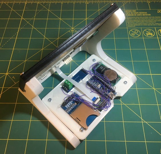
Step 6: Wire Wrapping the Entire Board
This shows the board after I wire wrapped all the connections. I made a few mistakes along the way, but these were easily undone by clipping the wires and using tweezers to unwrap the ends from the posts.
I suggest doing it one part at a time and checking your work with a multi-meter or by powering up and testing each component. Its a lot harder to fix once there are multiple layers of wires.
My finished product looks a bit messy, but if you want you can be a bit more careful about the routing or use different colors to keep things clear.
Even if it doesn’t look pretty, it is a lot more robust than a breadboard! But the big bonus is that if at any time you want to take it apart, you can do so easily with no damage to the Arduino Nano or to the pin headers on the individual boards!
Step 7: Compatible Projects
The completed board will allow you to implement these projects:
- 80s Style Melting Digital Clock
- An Illuminated Rainbow Piano With An Arduino (requires external components)
Source: Make a Custom Arduino Test Bench Using Wirewrapping