
Summary of Make A Arduino LCD Thermometer
This tutorial guides users in building an Arduino-based thermometer using an MCP9700 temperature sensor and a 16x2 LCD. The system reads temperature data from the sensor via analog pin A0 and displays it on the screen, demonstrating functionality by showing temperature changes when the sensor is touched.
Parts used in Arduino LCD Thermometer:
- Arduino Uno board
- USB cable
- Wire links
- Breadboard
- 47 ohm resistor (R1)
- 100nF capacitor (C1, C2)
- 10k potentiometer (RV1)
- 16 character by 2 line LCD
- MCP9700 Linear Active Thermistor IC (U1)
In this tutorial, a temperature sensor (MCP9700 linear active thermistor IC) and LCD are connected to the Arduino. The Arduino reads the temperature from the MCP9700 on analog pin A0 and displays the temperature on the LCD.
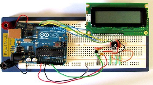
This video shows the circuit operating. When touched with a finger, the temperature sensor IC will measure an increasing temperature which is displayed on the LCD.
Can’t see the video? View on YouTube →
Also see the Arduino serial thermometer tutorial (Tutorial 15).
Prerequisites
Complete Tutorial 12: Arduino LCD before attempting this tutorial.
Components
Besides an Arduino Uno board, USB cable, wire links and a breadboard, you will need:
| Qty | Part | Designator | Notes | Type |
|---|---|---|---|---|
| 1 | 47 ohm resistor (yellow – violet – black) | R1 | 1/4W, 5% or better
Only needed if using LCD backlight |
Resistor |
| 2 | 100n | C1, C2 | Non-polarized | Capacitor |
| 1 | 10k potentiometer | RV1 | Trimpot or panel mount | Potentiometer |
| 1 | 16 character by 2 line LCD | LCD | LCD | |
| 1 | MCP9700 | U1 | Linear Active Thermistor IC | Semiconductor |
Circuit Diagram
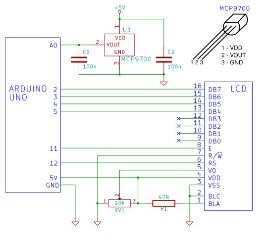
The MCP9700 IC is housed in a TO-92 package (it looks like a transistor). The pinout of the package is shown in the circuit diagram. Capacitors C1 and C2 are used to stabilise the output from the MCP9700 and stabilise the power to the MCP9700.
Building the Circuit
Follow tutorial 12 to interface the LCD to the Arduino. Connect the MCP9700 to the Arduino A0 pin as shown in the circuit diagram (pin 2 of the MCP9700 connects to A0 on the Arduino). Pin 1 of the MCP9700 (marked VDD) is connected to the Arduino 5V pin via the breadboard. The GND pin of the MCP9700 is connected to one of the Arduino GND pins.
Click the picture below for a bigger image of the breadboard circuit.
Programming the Arduino
Copy the sketch for the Arduino LCD tutorial (below) and paste it into the Arduino IDE.
For more detail: Make A Arduino LCD Thermometer
-
What components are required for this project?
You need an Arduino Uno, USB cable, wire links, breadboard, a 47 ohm resistor, two 100nF capacitors, a 10k potentiometer, a 16x2 LCD, and an MCP9700 sensor. -
How do you connect the MCP9700 to the Arduino?
Pin 2 of the MCP9700 connects to Arduino A0, Pin 1 (VDD) connects to 5V, and the GND pin connects to an Arduino GND pin. -
What is the function of capacitors C1 and C2?
The capacitors are used to stabilize the output from the MCP9700 and stabilize the power supplied to the sensor. -
Can the backlight be controlled without the 47 ohm resistor?
The 47 ohm resistor is only needed if you are using the LCD backlight. -
What package type does the MCP9700 use?
The MCP9700 IC is housed in a TO-92 package which looks like a transistor. -
What must be completed before attempting this tutorial?
You should complete Tutorial 12 regarding the Arduino LCD interface before starting this project. -
Where can I view the circuit operating demonstration?
The video demonstration is available on YouTube or within the provided article link.
