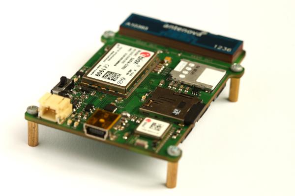
So here it is! Courtesy of Dangerous Prototypes Dirty PCB service, I have been able to put together and complete the testing of the first prototype of my very own location based development board. So lets talk about what you’re looking at. The board is a 4 layer PCB of dimensions 50 x 68 mm. The populated board has a maximum thickness of 9 mm. I considered using a 2 layer board, but the ground planes would not have been large enough and the substrate was too thick for the micro strip trace to the antenna to be of a realistic width. The microcontroller is running an Arduino Bootloader and the board is pictured on 7mm standoffs that are attached using M2 screws. Below is the in depth overview of the device. Click for larger versions.
On the topside of the PCB, working top to bottom, the device consists of:
- Penta-band GPRS/GSM/EDGE/HSPA/CDMA Antenna
- Antenna Matching Circuit
- Micro SIM Card Holder
- uBlox SARA-G350 GSM/GPRS Module (2.5G)
- Netwok Status Indication LED
- Standard Arduino LED
- Micro SD Card Holder
- uBlox CAM-M8Q GPS Module & Embedded Antenna
- Mini-B USB Connector
- F234XD USB-UART Controller
- Voltage Regulation
- Li-Po Battery Charging Controller via USB
- JST Connector for Battery
- Assorted Passives
On the bottom of the PCB, working top to bottom, the device consists of:
- Additional Voltage Regulation
- 3x Expansion Ports that use FFC Ribbon Cables
- ATMega2560AU Microcontroller
- Logic Level Converter
- Assorted Passives
For more detail: Location based development board

