Summary of 123D Scanner – Home made 3D Scanner
This article details a DIY 3D scanner project using Autodesk's free 123D Catch software. The device automates photography by rotating an arm around an object, capturing images for 3D model generation suitable for printing or viewing in various software. The design avoids rotating the object itself to ensure better stitching algorithm performance.
Parts used in the Home made 3D Scanner:
- MicroRax profiles and parts
- Full rotation servo (SpringRC SM4303)
- Cardboard scanning surface
- Colored stripes paint
- Nikon Coolpix L10 camera
- Small servo (DX.com servo)
- Metal block balancer
- Autodesk 123D Catch software
In this project I built a 3D Scanner, that enables generating 3D models of physical objects.
The files can later be viewed in 3D software (GLC Player, Sketchup, Rhino, or sites such as http://3dfile.io)
and even manipulated into .STL file and 3D printed.
The software for this project is completely free, I am using Autodesk’s 123D catch, Link:123D catch
The 123D Catch is a great software, it requires taking many photos of an object all around it, and uploading it into the software, and it returns a 3D file.
Since I really liked the solution but did not wanted to take the photos myself – I built an instrument that does that –
description hence.
Please note that this document does not intend to explain how to use 123D catch (this can be found here)
Step 1: Operation principle (can be skipped)
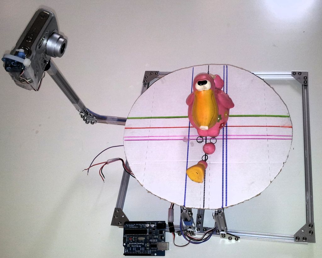
The design of the scanner is quite simple, and consists of 3 main parts:
- Scanner chassis and stage
- Scanner arm (carries the camera)
- Scanning surface
Each parts has it roles –
- The chassis – this is the part that sits on the table and carries the scanning Surface and the scanned object on it
- Scanner arm – The arm has the camera in the end of it, and a servo motor that presses on the button and take all of the pictures, the arm rotates around the scanning surface and takes pictures every few degrees. Pay attention that there’s a weight to balance the own weight of the camera (*)
- Scanning surface – a round board, with colored stripes on it, carries the scanned object. (**)
(*) The reason that the arm rotates around the object instead turning the object around is in purpose to make the stitching algorithm work easier, since if the object rotates, and the surrounding stays the same, the software work becomes complicated and the model doesnt work so well, environment -same as light sources shadows and all. (I did built one model with turned stage but the results were awful)
(**) The color stripes on the base are also in purpose to help the stitching algorithm – the help (colors, number of lines, orientation) to stitch.
Step 2: The chassis
It’s base is approx rectangular 30×30 [cm]
Step 3: The scanning surface
Step 4: The rotating arm
- Camera (Nikon Coolpix L10), any camera will do as long as its optical features can take photos in approx 10[cm] otherwise the pictures will become blurred and the 3D model will not be able to built.
- Small servo – that pushes the camera button, (any DX.com servo will work) I thought of hacking into the camera, but since it is my wife’s – i didn’t to it…
- Balancer – Metal block that balances the own weight of the camera and the servo and maintain the center of gravity on the axis of the rotation servo
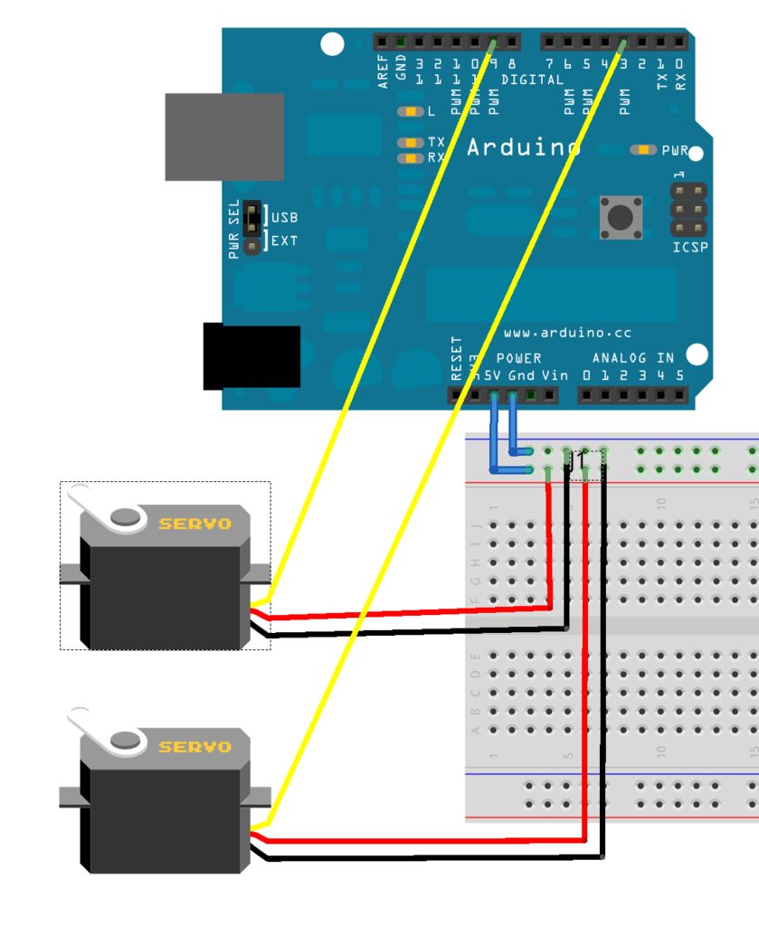
Step 5: Scanner assembly
This is quite straight forward, assemble the parts as seen in the pictures, ensure that the wires are long enuogh and will not get stuck during operation.
- What software is used for this 3D scanning project?
The project uses Autodesk's 123D Catch, which is completely free. - How does the scanner operate to generate models?
The scanner takes many photos of an object from all angles and uploads them to the software to return a 3D file. - Why does the arm rotate instead of the object?
Rotating the arm keeps the environment and light sources constant, making the stitching algorithm work easier and producing better results. - Can any camera be used for this project?
Any camera works as long as its optical features allow taking photos at approximately 10 cm without blurring. - What is the purpose of the colored stripes on the scanning surface?
The stripes help the stitching algorithm by providing colors, lines, and orientation cues for better image processing. - What material is used to build the chassis?
The chassis is built from MicroRax profiles and parts, forming a base of approximately 30x30 cm. - What component balances the weight of the camera?
A metal block acts as a balancer to maintain the center of gravity on the axis of the rotation servo. - Can the generated files be 3D printed?
Yes, the files can be manipulated into .STL format for 3D printing.