Several months ago I got a really good deal on a large 32×32 RGB LED matrix display. It matches up with the wiring interface shown on the Adafruit website for their 32×32 display so I did the usual testing with their libraries. Recently I was looking for some ideas for projects for this display. One of them that popped up was the Conway Game of Life. I didn’t find any versions that would run without modifications on the limited RAM space of the Arduino Nano so I wrote my own code. I did find, and borrow, a couple of code snippets that very concisely check the status of cell neighbors and implements the game rules.
The Game of Life made for an interesting display but I decided to see if I could make a symmetrical version so I ended up with a Snowflake display. Not one to leave well enough alone, I started to research some games that might suit this type of display. That led me to do a Snake game, a Pong game, and a Tetris game. Finally, I decided to see if all five versions could be shoehorned into the limited memory space of an Arduino Nano. It took some adjustments to the individual software pieces but it worked. Selection of which display or game to activate occurs when the Arduino is reset or power is turned on.
While this was mostly just a fun exercise, it was educational both in terms of working with the LED matrix and in exploring the rules and elements of the various games. In this Instructable I provide some tutorial information about working with the matrix as well as basic information about the various games and displays. There should be some useful pieces of the software here even if you don’t plan to build the entire project.
Step 1: RGB
If you already know everything there is to know about RGB (red-green-blue) color coding then skip this section. Basically, all it means is that each element of the matrix has three LEDs embedded in it. That means that you can vary the color of any given element based on which of the three LEDs you turn on. Obviously, you can get red, green and blue, but combinations of those three also give different colors. For instance, red and green and blue make white. It’s a trick of light sources so don’t mix red and green and blue paint and expect to get white. Red and blue make fuchsia (sort of pink), blue and green make cyan (pale blue) and red and green make yellow. Turn all three LEDs off for black. Not bad, eight colors from three light sources. Mathematically it is 2**3 and you get there by knowing that each LED has two states (on/off) and there are three LEDs.
So how can video displays and TVs advertise that they can get thousands or even millions of colors from RGB? Well, they can’t. What they actually do is to fool your eyes into thinking you are seeing all those different colors. Kind of like movie film makes your eyes think you see smooth motion when, in reality, you are seeing a rapid series of still photos. It looks smooth because the images are changing faster than your eye can detect. A similar principle happens with RGB to get all those other colors. For instance, if we turn on the red and green LED at the same time we see yellow. But let’s say that we turn on the green LED at half intensity. We would then see a different color. But the LED is only on or off so how do we get variable intensity? We do it by turning the green LED on only part of the time that the red LED is on. In order for this to work without eyeball detection we need to do the on/off times at a faster rate than the eye can detect. For example we could turn the green LED on/off with a 100-Hz square wave and it would appear to be at about half intensity. There are other factors involved but, for simplicity sake, that is a good rule of thumb. Mix that half intensity green with a full intensity red and you get orange. Pretty cool, but the more colors you want, the more levels of intensity you need, and the more processing power you need. For our 32×32 matrix, you need to serially shift 6144 bits of data for each display update. That actually results in only 1024 shifts because there are 6 color control inputs that get loaded for each shift. See the section on “Matrix Types” for further details
Step 2: Matrix Types
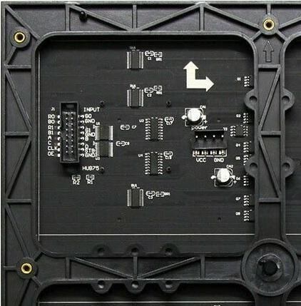
There are a variety of these matrices out there, with the most popular ones being 32×16 and 32×32. The Adafruit website has a bunch of terrific information to help you recognize and wire up your particular matrix. A picture of the connector labels for mine is shown above. When you are shopping for a matrix there are two terms that may not be well explained so I provide that information here.
Scan Rate: The “scan rate” refers to the number of individual addresses available for the matrix rows. The most common 32×32 versions are listed as “1:16” scan. What that really means is that each line has 32 pixels and it takes 16 different addresses (4 inputs) to cover all the lines. The reason it only takes 16 addresses is that the matrix is configured as two pieces of 32×16 – one on the top half and one on the bottom half. Each half has separate RGB color control inputs (6 total). You might think that the 32×16 displays out there would operate like a single half of a 32×32 matrix but that is not usually the case. The 32×16 displays are mostly listed as “1:8” scan with 3 address inputs. It can make the software a little complicated because you have to provide the bit information for a line in the upper half and its corresponding line in the lower half at the same time.
Pitch: The “pitch” specified for these matrix displays refers to the space between each RGB LED. Mine is one of the larger ones with a 7.62mm pitch and the whole display measures about 9 ½ inches square. There are several pitch values advertised so just remember that the lower the pitch number, the smaller the display.
Step 3: Hardware
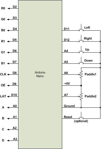
The hardware is pretty simple with four SPST normally open switches and two linear potentiometers. The potentiometers can be pretty much any value because they are just acting as variable voltage dividers for two of the Arduino Nano inputs. I’m using 5k potentiometers just because I have a bunch of them. Since I am using a Nano, I took advantage of the two extra analog inputs (A6 and A7) instead of having to use D0, D1, or D13 for any of my switch inputs. D13 is connected to the onboard LED so generally it’s not used as a digital port. D0 and D1 are for the UART connection and have a resistor inline on each pin. D0 and D1 should work ok if you want to use them as digital inputs and that is necessary if you want to host the software on any Arduino that doesn’t have A6 and A7 (like an UNO). Just move the potentiometers to A4 and A5, the Up/Down switches to D0 and D1, and make the appropriate changes to the define values in the Main software module.
A fifth switch can be added if you want a manual reset capability other than just cycling the power. One or the other of these methods is required to change to a different type of game or display.
Step 4: General Operation
The pixel ordering on a line can seem confusing. If you send 1 bit of data to a line, the right-most pixel lights up. However, if you send 2 bits, the first bit sent ends up in the second pixel from the right. That’s the nature of serially shifted data. In general you would always send all the bits for the selected line/address. For our 32×32 display that is 32 bits for each color and each half of the display, with the first bit sent ending up on the left side of the display. Remember that each of the 32 pixels on a line requires values of 0/1 for each of the 3 colors. On my display the inputs for the top half are labeled “R0, G0, B0” and the inputs for the bottom half are labeled “R1, G1, B1”. Some displays label them “1 and 2” instead of “0 and 1”.
Without using PWM to drive the color lines the maximum number of color combinations is eight. Here’s a list of available colors:
1. Black (all LEDs off)
2. White (all LEDs on)
3. Red
4. Green
5. Blue
6. Yellow (Red and Green)
7. Magenta (Red and Blue)
8. Cyan (Green and Blue)
Unlike the small matrix modules based on the MAX7219 chip, these matrices only remember the last set of bits sent. That means that if you change the address inputs, the LEDs on a different pair of lines will light using the same data. In some cases that may be a useful feature. There are several steps needed to display all matrix lines and these steps need to be continuously repeated. The steps are listed below:
1. Put a color bit on each RGB input. 1 turns the LED in that pixel on, 0 turns it off
2. Set the “CLK” (clock) pin high, then set it low
3. Repeat steps 1 and 2 for all pixels on the line
4. Set the “OE” (output enable) pin high (disables the display output)
5. Set the address lines (“A, B, C, D”) as needed
6. Set the “LAT” (latch) or “STB” (strobe) pin high, then set it low
7. Set the “OE” (output enable) line low (turns on the LEDs for this address)
8. Go back to step 1 after a delay (or use a timer interrupt)
Step 5: Software
It requires a high speed processor with lots of RAM to get the full capability out of these matrices. You need to do PWM on each color line and you need a byte for each color in each pixel to set the intensity. My goal was to do some simple but entertaining displays and games. Because I only needed simple colors and basic on/off pixel capabilities, I was able to map the entire display as an array of 32 unsigned long integers (32 bits each). The “Game of Life” and “Snowflake” displays require double buffering of the pixels but that still only amounts to 256 bytes of RAM. That also simplifies the code so I was able to easily fit all five variations into the Nano memory. Interestingly, the memory usage increased significantly when I added code to draw letters and numbers for start/end of game purposes.
When the software starts there is an option to choose which of the displays/games you want. A short press of any of the direction switches is used to move through the choices. If you are playing one of the games and it finishes, you can start that game over again without having to reset the Nano. A short press on any of the switches (other than the reset switch) will start a new version of the same game. Switching to a different game or display type requires a reset or power cycle of the Arduino.
The various game switches are defined at the top level but only connected to interrupt handlers as needed for each individual game. The switches are connected to Nano pins that allow the “interrupt-on-change” function. The top-level software has the actual interrupt handlers which, in turn, call the software routines for the active game.
There is a variable called “cycle_time” that dictates the rate at which each display is updated to a new version. That is separate from the refresh rate of the matrix but is dependent on the refresh rate. Each display/game initializes the appropriate value of “cycle_time”. Lower values speed up the rate of change.
The pixel colors are defined in each game for the various pieces. Generally, there are only two colors used. The colors for the “Game of Life” and “Snowflake” displays can be set by the define “Num_Colors”. The defined colors are the six other than white and black. Each display generation is all one color but the color changes with each generation change.
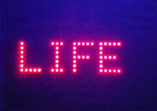
The text displays for start/end of game are pretty simple. Each letter/number is manually built from a 5×7 dot pattern with a single column of LEDs as spaces between characters. That only allows a maximum of five characters per line and a maximum of four lines. Not much to work with but enough for our purposes.
Step 6: Game of Life
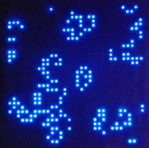
This isn’t really a game you play, rather it is a morphing display that follows specific rules. The basic “Game of Life” rules apply to this software version and new generations occur about once a second. While researching this I found that most implementations tend to have a problem with ending up in a static state. In some cases the population may become extinct and in other cases it may just repeat simple patterns. This is due, in part, to the fact that some clusters of cells will either stay exactly the same or they will oscillate between two patterns. The whole theory behind this is interesting if you wish to explore it further. There are various methods used to overcome this static state. My solution is to periodically introduce a pattern that moves across the display (called a large spaceship). If it hits a static pattern it can free it up. Just think of it as a ship full of aliens being introduced into the population every millennium or so.
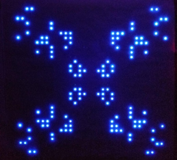
Step 7: Snowflake Display
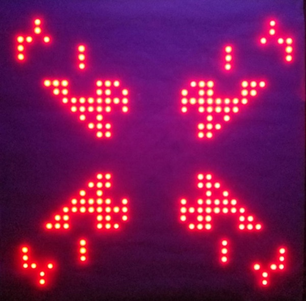
This is actually a variation of the “Game of Life” display. Instead of randomly populating the initial display, it is started with a symmetrical set of patterns called gliders. Gliders are patterns that move along a specific diagonal path across the display. I took the basic glider pattern and modified it so that I had separate ones that would move in each of the four board directions. A new set of gliders is introduced fairly often and the result is an ever changing “snowflake” pattern display.
Step 8: Snake Game
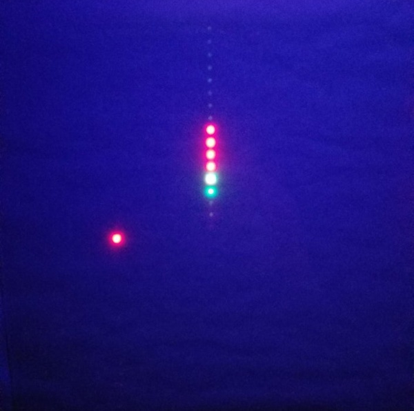
There are a variety of versions of the snake or worm game. The basic idea is to grow the snake and to avoid leaving the board boundary or hitting any part of the snake itself. In my version, the snake starts out with a few segments and grows each time it eats an apple. A new apple appears each time one is eaten. As an optimist, I set the maximum snake size to a few hundred segments but I haven’t played it long enough to approach that limit. You can increase that amount somewhat as long as you stay within the limits of the available RAM. The body of the snake and the apples are red and the head of the snake is green.
Step 9: Pong Game
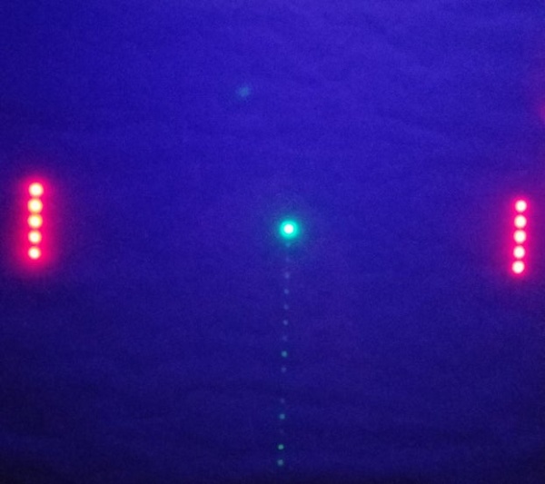
This is the simple two paddle game. The paddles are moved up and down using potentiometers instead of the switches and the voltage of the potentiometer is read as an analog input. Each paddle uses five pixels and the direction of the ball off of the paddle depends on which segment the ball hits. The paddles are red and the ball is green. There is a couple of seconds of delay at the start so that the players can adjust their paddles. It should be noted that the value of “cycle_time” for this game is set as fast as possible. It’s not really fast enough to be a great challenge but that’s a limitation of the processing throughput of the Nano.
Step 10: Tetris Game
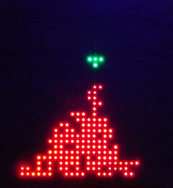
This is a simple version of Tetris that uses a set of seven shapes (I, O, T, J, L, S, Z). The shapes are dropped from the top at a fixed speed but there is no provision for speeding up the rate like in some versions of Tetris. Each dropped shape is randomly selected in the software and they can be moved right or left or rotated as they fall. The Up/Down switches control the rotation. Each time a line is filled it is removed and all lines above it are moved down. The dropping shape is green and it changes to red once it stops at the bottom of the accumulated shapes.
Source: Life and Tetris and Pong…Oh My!