This project uses LED lights controlled by an accelerometer and gyroscope to challenge your skateboarding creativity. The LED lights change according to what trick is being performed. For example, a shuvit (180-degree yaw rotation) changes the lights blue. a kickflip (360-degree roll) changes the color to red. when both tricks are done simultaneously (varial flip) the colors are added together, turning the lights purple. This functionality of adding colors challenges the skater to come up with new trick variations to create interesting colors.
Supplies
9 volt battery
wires for soldering
switch (not sure what its called any small switch works)
Step 1: Basic Concept / Logic
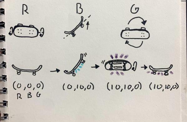
The basic concept is using additive colors to change the R B G values of the LED strip. Each value is controlled by a different trick. just popping the board up, like an ollie) represents blue. A kickflip represents red, and a shuvit represents green. Each time a trick is performed 10 is added to the respective R B G value.
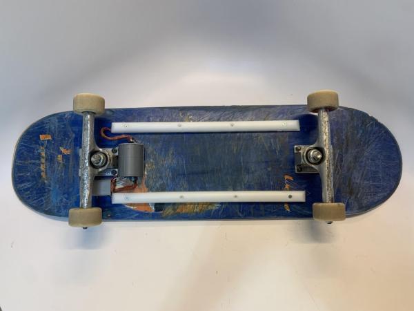
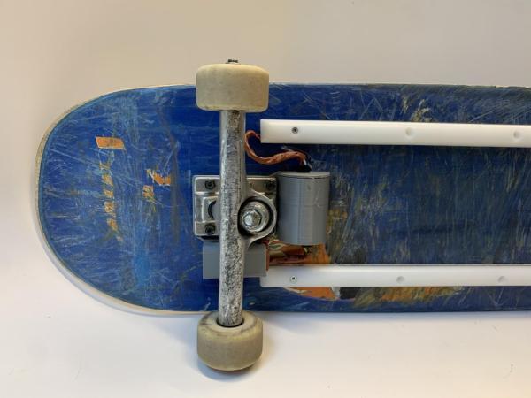
Step 2: LED Strip Assembly
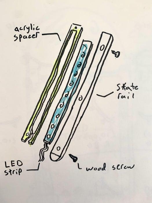
Cut the spacer out of acrylic using the attached file. glue the spacer to the rail using super glue. Make sure there is enough space for the LED strip. Cut the LED strip 18 LEDs wide and glue it LED down to the rail. Make sure it’s fully nested in the spacer.
Step 3: Soldering and Arduino Assembly
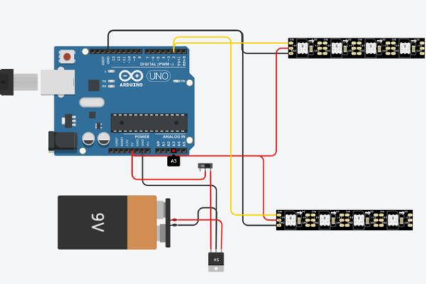
The circuit for this project is actually very simple. The hard part is getting it compact enough to fit in the enclosure. I soldered the male to female header pins to the breadboard so the Arduino can be removed however you can solder the nano directly to the breadboard. I also taped the voltage regulator to the 9v connector. finally I soldered the connectors to the LEDs to the board and tucked them under the nano. It takes a while to get everything neat and tidy but it’s worth it to secure everything down. finally hot glue the electronics to the housing. This is more important than I thought because skateboarding is really hard on electronics and the componentac can easily come undone (even with hot glue).
Step 4: Electronics Housing
The file attached is the housing for the electronics. please note this file is far from perfect and needs revisions and modifications to make the electronics fit. The housing is sandwiched between the truck and the deck. I also hot glued the whole housing to the deck because the plastic can break off with the hard impacts of skateboarding.
Step 5: Code
first want to say thank you to @owennewo on github for his gyro and accelerometer code. I used the code from this file to read and filter gyro and accelerometer data. I learned very quick that the accelerometer and gyro from the nano is really bad and the values drift all over the place. This is why you need a filter to help with the drift and get more accurate angle readings. Basically how the code works is if the gyro reads over a certain angle, a flip is recorded and 10 is added to the respective R B G value. The code is in need of a lot of adjustments and I would love help from the community!
Code: https://github.com/mileslew/LED-Skateboard-gyro/b…
Source: LED Skateboard Rubiks Cube