
Summary of LED Hour Glass
This article details the construction of an interactive LED hourglass that simulates falling sand using WS2812B LEDs and an accelerometer. The project involves building a wooden frame, mounting LEDs on a backerboard in a specific pattern, wiring the electronics to an Arduino (or ESP8266), and programming the device to react to tilt and orientation changes for dynamic animation effects.
Parts used in the LED Hour Glass:
- WS2812B LED strip
- 5V power supply
- MMA8451 accelerometer
- Arduino Mega or ESP8266
- Scrap wood for the frame
- Purple heart wood strips for the border
- Backerboard
- Hot glue
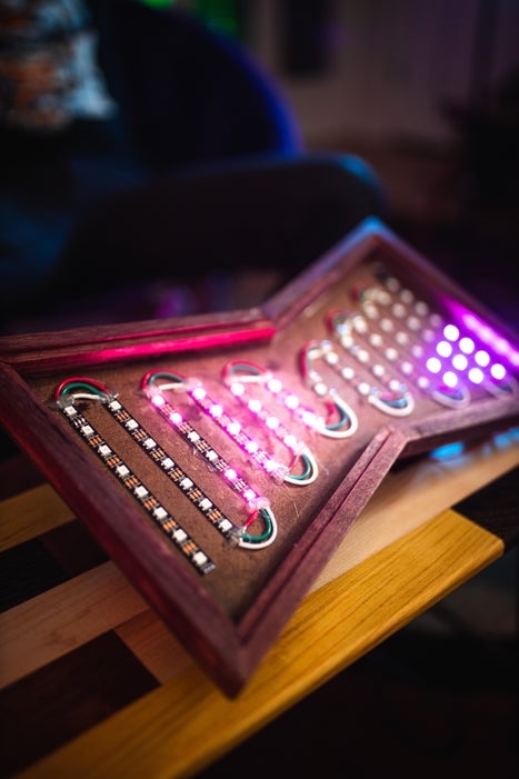
In this article I describe how we made an hour glass with leds as the sand. We were always interested in making something that visually flows like sand and decided to use an hour glass to start. The movement is not completely fluid given the resolution of the amount of pixels, but it does resemble sand falling down and reacts to tilting and orientation changes. Keep reading and watch the video to find out how we did it!
Supplies
- ws2812b led strip – https://amzn.to/38W7uPt
- 5v power supply – https://amzn.to/38TTplk
- MMA8451 accelerometer – https://amzn.to/39JJVsb
- arduino (I recommend the esp8266 but I used a mega) – https://amzn.to/2XQtnsP
Step 1: Make What Will Be the Frame of the Hour Glass
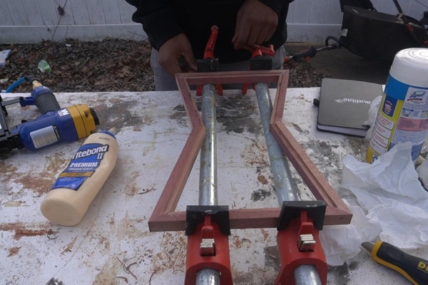
We used some leftover scrap wood to make the frame for the hour glass. The ends of both the top and bottom pieces of the frame were cut at 37.5 degrees each and the other 4 pieces that made the left and right sides were cut at 37.5 degrees on one end and 15 degrees at the other. The end that was 37.5 degrees was joined with the piece that made up the top/bottom of the frame. This made a 75 degree angle that formed the inside of each corner of the hour glass (37.5 + 37.5 = 75). This meant that we were 15 degrees from 90 on each end, which is why we cut the other end of the 4 side pieces to 15 degrees. This made the seem that connected each half of the hour glass completely flat. After we glued up the frame we used it as a template to cut the backerboard which will hold the leds.
Step 2: Add the Leds to the Backerboard
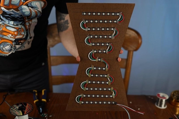
In this step we added horizontal strips of leds to the backerboard. The highest row had 8 leds while each row lower was 1 less in value up to 3 leds. Then we had a center led that was a single led before going to 3 leds for the start of the row in the other half of the hour glass. We connected each row in a snaking pattern to maintain the data path of the ws2812b led pins. We used hot glue to secure each connection, and made sure to test the connections out before securing with hot glue to ensure we didn’t have to rip it out and try again.
Step 3: Make the Circuit
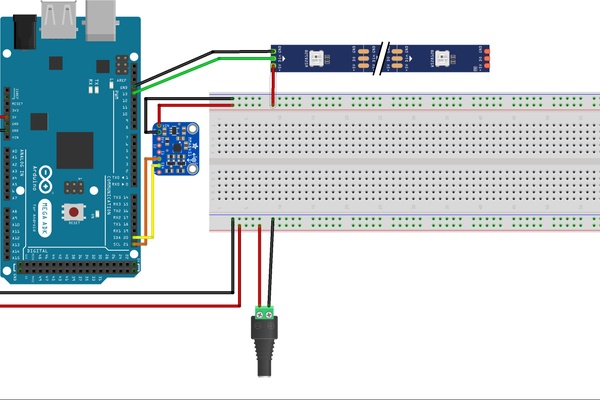
The next step is to make the circuit. Following the circuit diagram connect the 5v power supply to the arduino and led strips. Make sure to also connect the accelerometer to the sda/scl pins of the arduino. This is important to note: The starting orientation of your accelerometer matters. If you hook yours up in a different orientation than we do, then you’ll need to modify the code to ensure you are using the correct boundary numbers when rotating the hour glass.
Step 4: Finish Up the Structure of the Hour Glass
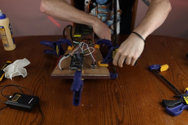
Now that the electronics are hooked up, go ahead and finish gluing/sanding/applying finish to the structure that is your hour glass. If we were to make this over again, we would definitely make the border thicker. We used some leftover strips of purple heart wood as the border but we would definitely use a thicker border that can hold the power supply and the other heavy electronic components upright when just standing there.
Step 5: Apply the Code
Repository: https://github.com/tmckay1/led_hour_glass/tree/mai…
Not to go into too much detail of the code, we’ll outline the basic design of the hour glass. We have a cycle that occurs in code which is the completion of 1 frame of an animation. So a cycle in our case is the grain of sand dropping and piling up on the bottom while losing a grain from the top. Each cycle has 6 frames of animation. The first frame is the top piece of the hour glass dropping off and filling the center of the hour glass. The second to fifth frames are the sand dropping from each row there after, and the last frame (sixth frame) we add an led to the bottom of the hour glass to increase the count.
Now on each iteration of the arduino loop, we read the current coordinates of the accelerometer and determine the y-direction of the hour glass (if we are up, down, or horizontal), and the tilt direction (tilted left, right, or completely upright with no tilt). Based on the orientation from reading values in the accelerometer, we will either animate the sand dropping down or not. When tilted we draw the sand tilted to the side, otherwise we draw it dropping upright. To determine how to draw the leds based on the tilt, we have 4 different structure arrays that dictate how the shape will look based on the number of leds each half has.
There are 4 structure arrays and there can be no more on an arduino Mega due to memory issues. If you use a esp8266 you could add even more structures. The structures are: dropping sand from the top and animating the pile losing an led, accumulating sand on the bottom upright, accumulating sand on the bottom tilted right, and accumulating sand on the bottom tilted left. You can try and be clever and make even more structures by computing the coordinates on the tilted side, but you will run into overflow issues and the animation will be garbled. I recommend just using an esp8266 if you’d like a better fps animation.
Step 6: That’s It!

The code assumes you start out in a straight upright position, so after uploading the code, enjoy!
Source: LED Hour Glass
-
What materials were used to construct the frame?
The frame was built using leftover scrap wood with specific angle cuts of 37.5 degrees and 15 degrees to form the corners. -
How are the LEDs arranged on the backerboard?
Horizontal strips are added where the highest row has 8 LEDs, decreasing by one per row down to 3, with a single center LED separating the two halves. -
Can I use an ESP8266 instead of an Arduino Mega?
Yes, the author recommends the ESP8266 because it allows for more structure arrays and better FPS animation without memory overflow issues. -
Does the orientation of the accelerometer affect the code?
Yes, the starting orientation matters; if hooked up differently than shown, you must modify the code to use correct boundary numbers. -
How many frames make up one complete cycle of the animation?
A complete cycle consists of 6 frames of animation representing the grain dropping and piling up. -
Why did the authors suggest making the border thicker?
A thicker border would be better able to hold the power supply and heavy electronic components upright when standing alone. -
How does the device determine when to animate the sand?
The code reads coordinates from the accelerometer to determine if the glass is upright or tilted left/right, triggering the appropriate animation. -
What limits the number of structure arrays in the code?
Memory issues on the Arduino Mega limit the structure arrays to four; adding more causes overflow and garbled animation.
