The idea for this Arduino phototransistor project came to me based on an idea that was shared by one of my friends at the FabLab. He talked about how his lab only has stools for people to sit on. Being very uncomfortable, the person succumbs to the discomfort and stands up to move around. In our case, we had very comfortable rolling chairs for sitting and reclining, which can get you lazy and even sleepy real quick.
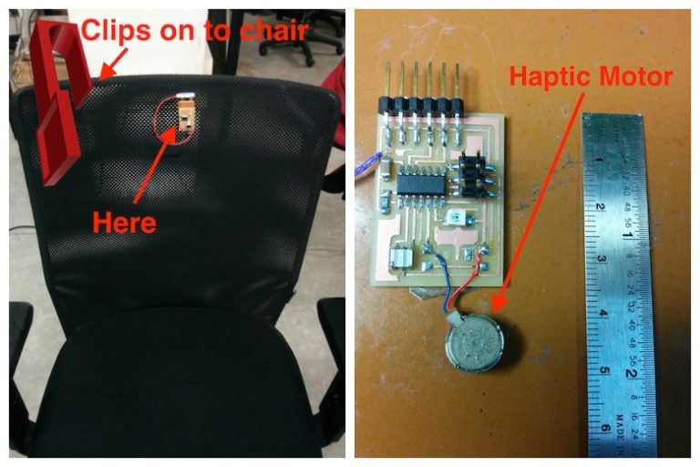
In this project, I wanted to solve that problem by creating a sleek gadget which when plugged into our chairs, will prompt the user to get up if they are sitting continuously for more than 10 mins. It does this by using a haptic feedback motor, and it will only notify the person sitting on the chair, instead of disturbing others around him (if I were to use other means like sounds/lights).
This Arduino phototransistor project consists of three stages:
- Preparing the electronics with the help of Modella
- Programming
- Designing and printing it using the Ultimaker
How Does it Work?
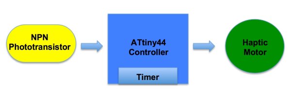
The NPN phototransistor signals the ATtiny44 when there is no light (this is the case when a person is sitting on the chair). After which the controller starts a timer. If the timer exceeds 10 minutes, then it immediately activates the haptic motor, which prompts the user to get up.
Required Materials
- NPN plcc 2 phototransistor
- ATtiny44 controller (Arduino works too)
- 20MHz crystal
- 10K resistor
- 6 pin (3×2) header 2nos
- 1uF SMD capacitor
- 9V battery and clip
- Haptic motor
Electronics and Programming
I used this tutorial to learn about phototransistors. The NPN phototransistor will be used with a floating base and the emitter connected to ground. The collector needs to be pulled up to Vcc through a resistor (I am doing this with the internal pull-up resistor). When the phototransistor detects light (the collector and emitter are shorted) it outputs a logic LOW voltage and a logic HIGH voltage when there is no light. The configuration:
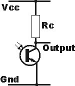
I started off by using my HelloWorld board milled from the Modella and de soldering the button from it. I then attached the phototransistor to ATtiny pin no: 7. I found out that the notch in the package of the phototransistor represents the collector terminal. I learned this from the VEMT3700F NPN Transistor datasheet (PDF). Another resource worth checking out is the TT Electronics Optek Technology resource guide. You can also just use an Arduino board and connect the phototransistor to the Arduino’s digital pin 7 and use the same code shown below.
Read More: Arduino Phototransistor and Haptics Project