Summary of Laser Pointer Switch using arduino
This article details building a light-activated switch using an Arduino. The project samples ambient light with a photoresistor; when readings exceed a set threshold, it triggers a relay to control small appliances like lights or fans. The build involves modifying a USB cable for power, soldering components directly to the Arduino board, and uploading custom code to manage the switching logic based on light intensity.
Parts used in the Laser Pointer Switch:
- Arduino board
- Relay module
- Photo cell (photoresistor)
- Resistor
- Right angle header
- USB cable
- FTDI device
- Soldering equipment and tape
This instructable will detail how to make a switch that uses an arduino to sample light. When the light sample reaches a threshold it will trigger a relay that can be used to turn on/off a small appliance (light, radio, fan, etc…) The parts for this instructable can be ordered as a kit:
http://www.jameco.com/webapp/wcs/stores/servlet/Product_10001_10001_2209967_-1
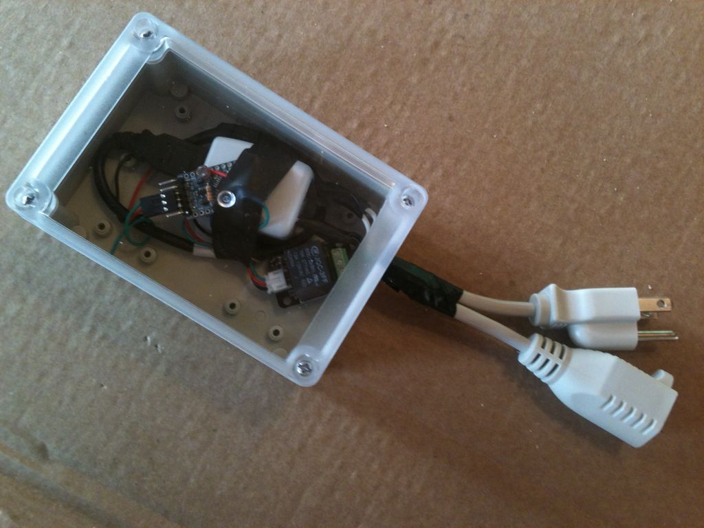
Step 1: Review relay and prep wire
unpackage the relay and stretch out the cable. this cable is used to activate the relay but will also be used to power the arduino. cut the wire in about two equal parts. the part with the white clip end will plug into the relay and be soldered into the arduino. the wire with the black clip end will be spliced into the usb cable to supply power to the arduino. this is also a good time to review the relay tutorial for safety information: http://www.dfrobot.com/wiki/index.php?title=Tutorial:_DFR0017_V2_Relay
Step 2: Modify USB cable
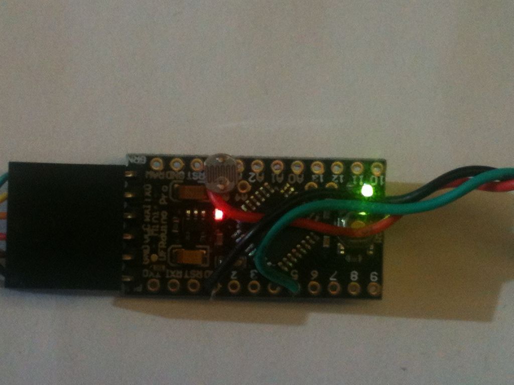
Step 3: Identify Arduino
Step 4: Component Layout
Step 5: Solder Arduino
Step 6: Program Arduino
//adjust the lTrigger number for your light values
int lTrigger = 610;
int photoPin = A5; //define a pin for Photo cell
int ledPin=5; //define a pin for relay activator
boolean bLatch = false;
int lLaser = 0;
void setup() {
Serial.begin(9600); //Begin serial communcation
pinMode( photoPin, INPUT );
pinMode( ledPin, OUTPUT );
}
void loop() {
lLaser = analogRead(photoPin);
if (lLaser > lTrigger) {
bLatch = !bLatch;
digitalWrite(ledPin,bLatch);
delay(1000);
}
Serial.println(lLaser); //display photocell value to serial monitor.
delay(10); //short delay for switch bounce
}
test your arduino with the serial monitor open to see the light reading values. adjust the trigger value to a range that works best with your laser pointer.
- How is the Arduino powered in this project?
The Arduino is powered by splicing the red and black wires from the relay cable into a modified USB cable. - Where does the photo cell connect on the Arduino?
One leg of the photo cell goes into the A5 hole and the other leg goes into the Vcc hole. - What happens when the light sample reaches a threshold?
Reaching the threshold triggers a relay that can turn on or off a small appliance. - Can I adjust the sensitivity of the light sensor?
Yes, you can adjust the lTrigger number in the code to match your specific light values. - What should be done if component legs do not fit in the same hole?
You can put the resistor in from the back of the Arduino and connect the photo cell leg to the resistor leg behind the board. - Which pin is defined for the relay activator in the code?
Pin 5 is defined as the ledPin for the relay activator. - How do you test the Arduino after programming?
You test it by opening the serial monitor to view the light reading values and adjusting the trigger range. - What is the purpose of the white clip end on the relay cable?
The white clip end plugs into the relay and is soldered into the Arduino.