Summary of Knockdown Warning Indicator (Redux)
This week the author advanced a knockdown-warning device for sailing ships that measures heel with an accelerometer and indicates gust-risk via LEDs for 60, 45, or 30-knot gust thresholds. Design centers on an ADXL335 3-axis accelerometer on a removable sensor board with low-pass filters, interfacing to an ATMega88 microcontroller, powered via USB with a 3.3V regulator. The modular board allows testing multiple sensors; development hit a hardware hiccup when the regulator smoked, possibly due to a cable.
Parts used in the Knockdown Warning Indicator (Redux):
- ADXL335 3-axis accelerometer
- Single-axis accelerometer (stock)
- ATMega88 microcontroller
- ATMega328p referenced in make file
- 3.3V voltage regulator
- USB power cable (5V supply)
- Three LEDs (for 60, 45, 30 knot indications)
- Passive low-pass filter components (resistors and capacitors) on sensor board
- 2x3 pin connector (for sensor board to main board)
- Zero-ohm resistor placeholders (for filter tuning)
- PCB / separate sensor board
This week I continued developing a device that warns of the potential of a knockdown – the process by which an over-canvassed sailing ship is lain over on her beam-ends during a squall. The potential for sinking at this point is high, especially if there are hatches open on the leeward side, so it is an event to be avoided. As the reading of squall curves (from vessel stability booklets) is a skill rarely practiced these days, such a device has merit. A squall curve diagram generally indicates the maximum angle of heel recommended for a given wind velocity, and the potential for gusts. The 210’ tall ship Concordia sank in 2010 in such an event.
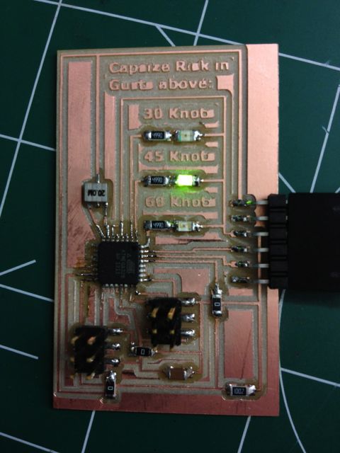
At a basic level, assuming a prevailing wind of 25 knots (beaufort force 6), this device will measure heel (inclination) and indicate the level of gust that would present a knockdown risk based on that angle of heel, by flashing a LED for either 60 knots, 45 knots or 30 knots.
I based the design around an accelerometer, with the plan being to trial more than one. The sort we have in stock is a single axis, but Lindy had an ADXL335, 3-axis (one of the new ones, and it was around this that I designed the circuit. With three axis inputs, and three LED outputs, I needed to use the ATMega88 – new for me.
Data sheets for ADXL335 and ATMega88.
Excellent resources for using the ADXL335:
http://www.electronicsblog.net/simple-angle-meter-using-adxl335-accelerometer-arduino/
http://www.evilmadscientist.com/2007/using-an-adxl330-accelerometer-with-an-avr-microcontroller/
Here’s my schematic.
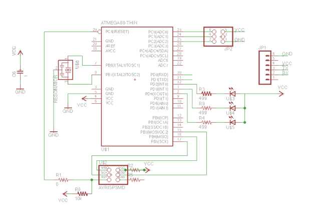
I designed the circuit so that the accelerometer resided on a separate board with three passive lo-pass filters that would connect to the main board via a 2×3 pin arrangement. I set the board up this way so that I could experiment with several accelerometers, hoping to ultimately build my own using a flexure.
The ADXL335 has resistors built in resistors so technically I don’t need the ones in the above diagram, and they are zero ohm. I included them on the advice of a former technical director at RIM who said she always made provision for them, so she could tweak the filter later if necessary. Used a 3.3V Voltage Regulator to adjust from the 5V that is supplied via USB.
Board took code, after fiddling with the make file (AT Mega 328p – I was missing the p). Unfortunately there was a puff of smoke from the voltage regulator when I plugged the accelerometer board in. I’m suspecting my cable. Not sure whether the Accelerometer is still functional.
The embedded code has the LEDs flashing on a loop with a delay.
For more detail: Knockdown Warning Indicator (Redux)
- What does the device measure?
It measures heel (inclination) using an accelerometer. - Which accelerometer is the design based around?
The design is based around the ADXL335 3-axis accelerometer. - What microcontroller is used?
The project uses an ATMega88 microcontroller. - How are gust-risk levels indicated?
Three LEDs flash to indicate gust-risk thresholds of 60 knots, 45 knots, or 30 knots. - How is the sensor board connected to the main board?
Via a 2x3 pin arrangement connecting the sensor board to the main board. - Why are zero-ohm resistors included on the sensor board?
They were included as placeholders so the filter can be tweaked later if necessary. - What power supply and regulation are used?
The device is powered from 5V via USB and uses a 3.3V voltage regulator for the accelerometer. - Can multiple accelerometers be tested with this design?
Yes, the separate sensor board layout allows experimenting with several accelerometers. - Did any hardware issues occur during testing?
Yes, a puff of smoke came from the voltage regulator when the accelerometer board was plugged in, possibly due to the cable. - What does the embedded code currently do?
The embedded code has the LEDs flashing on a loop with a delay.