Introduction
For the third assignment, we decided to make a ‘knock-detector’ that is capable of informing the user/owner of specific events. We designed our system such that it can detect both casual knocks and knock patterns. Casual knocks could be used to inform the owner/user that someone is at door, which may be particularly useful for the deaf or in situations where it is difficult to hear the knocking sound. Specific knock patterns could be used for more complex tasks like providing access control to specific areas, or turning on and off a light switch.
This project was in part inspired by the class video on detecting taps, as well as the fact that we at HCIL are still working on an access control system for the Hackerspace.
Components
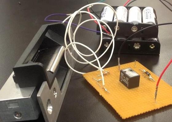
We implemented our system using an Arduino Uno, with several attached components. Below is a diagram of our circuits containing the complete system:
Knock Detector
We used a piezo-electric vibration sensor to detect knocks. It connects to the ground and one of the analog pins on the Arduino Uno, and generates a small voltage whenever it experiences a vibration.
RGB LED
Our system uses an multi-color LED to give visual indications of what state the system is in. We used a common anode RGB LED which consists of four pins – one shared input from the 5 V pin on the Arduino, and a separate output pin for each of the red, green, and blue color channels, which are connected to input pins on the Arduino. We used digital pulse width modulation pins (PWM pins 3, 5, and 6 on the Arduino Uno), which can simulate an analog output over digital by rapidly turning on and off the circuit at different frequencies. This allows us to display full 24-bit color over the LED.
Electronic Door Strike
In addition to the primary application described above, we wished to demonstrate the additional applications of our system. In particular, we wanted to be able to use a secret knock as an access control method. This is possible using an electronic door strike, enabled and disabled from the Arduino as the vibration patterns are analyzed.
The door strike we used required approximately 12 volts to operate, more than our Arduino could provide. We used two separate circuits connected through a relay, with the Arduino controlling a switch on the higher voltage circuit. When the relay receives power from the Arduino, it activates a magnetic coil inside it which physically moves a switch inside selecting between two loops on the higher powered circuit. By default, the relay directs power through a resistor and nothing else. When activated the power is routed through the electronic door strike, unlocking it.
We use a diode in parallel with the relay on the Arduino circuit to help protect it from back voltages. The two circuits passing through the relay are completely unconnected, and so in theory there should be no risk of the higher voltage passing through to the Arduino. However, because the relay generates a magnetic field and because there may be some voltage buildup at the resistor when the door strike is powered off, it is possible that some electricity may be transferred to the Arduino circuit at an extremely high voltage that could damage the micro-controller. The diode helps to prevent this.
Wifi Shield
We use Twitter to send event notifications to the user, but this method could easily be applied to sending out email or text-messages. A WiFi shield allows us to connect the Arduino to the internet, although it is limited WPA/WEP personal wifi networks. Because the technical limitations of the current WiFi shield prevented us from connecting to the university’s wifi networks, we needed to create a local network connected to a UMD ethernet port. This has the added benefit that the device connects quickly to the network and the signal remains strong throughout the room. The WiFi shield has the same pin arrangement as the Arduino UNO, and so we could easily place it over the micro-controller without reducing the pin availability. We did run into some minor technical issues when connecting our circuits to a couple of the pins, as they seem to interact in some capacity with the wifi components. However, it is unclear exactly what was causing this problem, and our system works correctly using the pin layout in the circuit diagram above.
Software Design
Knock Pattern Recognition
The voltages we read from the piezo-electric vibration sensor are higher the stronger the vibration is. However, there are multiple factors that prevent the readings from being the same every time, even assuming a knock with the same force. For one thing, different door thicknesses and materials have different sound conductivity properties and so will cause the sensor to vibrate more or less in different situations. For another, the vibrations take some time to dissipate, and even after the voltage has dropped to zero the sensor seems to take some time to reset. This means that when there are two identical knocks within less than a tenth of a second of each other, the second almost always generates less voltage. We compensate for this by setting a fairly low threshold for detecting a knock, although we still have to calibrate this value for different materials.
We use a double threshold approach for detecting when a knock has occurred, triggering the start of a knock when the voltage reading passes the higher threshold and stopping it once it drops below the lower threshold. We then find the peak voltage and perform non-maximum suppression to localize the knock in time.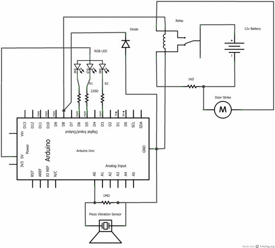
To minimize the effect of errant vibrations, such as wind or someone bumping into a door accidentally, we don’t send a notification unless there are at least two knocks and the distance between the knocks is less than a second.
We save the timings between knocks, which we can then compare against a knock pattern to determine whether it is a match. To allow for variations in tempo, we first normalize the timings by dividing them by the maximum time between the detected knocks and multiplying by one hundred. If, after normalization, the maximum and average distances between the detected timings and the pattern are both below their respective thresholds, then the appropriate action is applied (such as unlocking an electronic door strike).
Wifi Connection
To connect to a WiFi network, we used a WiFi Library. The library allows us to connect to WPA Personal or WEP networks only. WPA Enterprise is not currently supported, and so the UMD wifi networks could not be used. A single command with the network username and password will connect the Arduino to internet.
For more detail: Knock Detector