This Instructable is a variant of the original IV Swinger 2:
https://www.instructables.com/id/IV-Swinger-2-a-50-IV-Curve-Tracer/
If you came here from there, welcome!
Otherwise, please visit that Instructable first. You may or may not end up back here depending on which variant you have chosen..
Step 1: Understand the HW Design / Choose Variant
Please refer to Step 1 in the original Instructable:
https://www.instructables.com/id/IV-Swinger-2-a-50-IV-Curve-Tracer/
If you are back here, it means you have chosen:
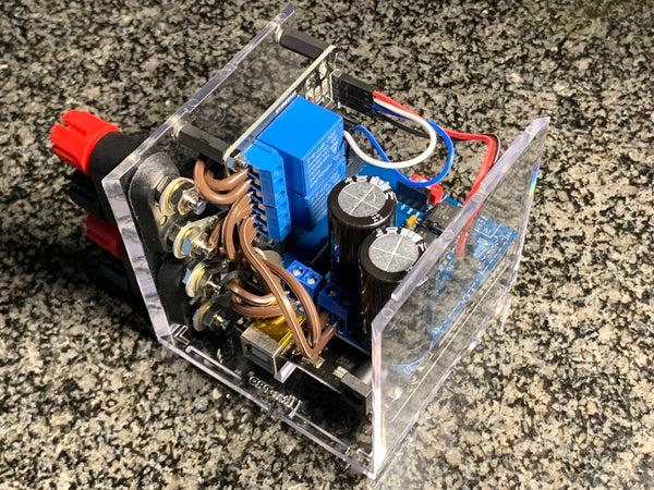
PCB – PV cell version, electromechanical relay (EMR)
Attached to this step are the following:
- PDF of the steps of this Instructable
- PDF of the schematic of this version
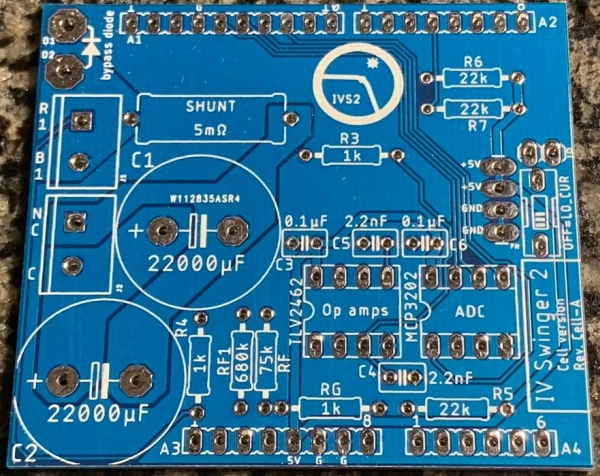
- PDF with images of the top and bottom of the PCB
Step 2: Install Software
Before spending time building the hardware, install the Arduino software and the IV Swinger 2 application on the laptop that you’ll be using.
- Install Arduino IDE:
https://www.arduino.cc/en/Main/Software
- Install IV Swinger 2 app:
https://github.com/csatt/IV_Swinger/releases
Make sure both of the above come up before proceeding. If necessary, upgrade the OS on your computer
Step 3: Order PCB
Currently, the PCB must be purchased from a manufacturing house that will actually fabricate it for your order. The downside of this is that you’ll probably have to buy more than you need. I have used the following two:
OSH Park:
- https://oshpark.com
- Made in USA
- Cost: $25 for 3 PCBs (includes shipping)
- Time: < 12 days to ship
PCBWay:
- https://www.pcbway.com
- Made in China
- Cost: $5 for 10 PCBs + shipping ($16 DHL to CA)
- Time: < 5 days to ship
Amazingly, I have put in orders to PCBWay on a Monday and had the boards in my hands in California on Friday.
I have shared this PCB design on PCBWay, and you can order it directly using the following link:
https://www.pcbway.com/project/shareproject/IV_Swinger_2_cell_Rev_A_2019_01_06.html
Alternately, you can order PCBs from OSH Park (or anywhere else) by uploading the ZIP archive of the Gerber files, which are found in the GitHub repository:
IV_Swinger/PCB/IV_Swinger_2_cell/Gerber/*.zip
Soon, I hope to find someone who wants to sell individual PCBs on eBay (possibly in kits, that include all the other parts too).
Step 4: Buy Other Parts
The other necessary parts to build an IV Swinger 2 can all be purchased online from Amazon and Digi-Key.
The EMR PV cell version bill of materials (BOM) is attached to this step. It can also be downloaded from:
https://github.com/csatt/IV_Swinger/raw/master/PCB/BOM/emr_cell_BOM.pdf
The BOM has an Amazon link and a Digi-Key link at the bottom. The Amazon link is a “wish list” that can be used to populate your cart. Some of the items come in quantities larger (in some cases much larger) than needed to build a single IV Swinger 2. You may, of course, choose to find equivalents that are offered in smaller quantities. Also, many of the items are things that you may already have, so don’t necessarily just blindly order everything on the list.
The Digi-Key link is a pre-populated shopping cart. Again, you’ll want to check if you already have any of the items before ordering.
In both cases, it is possible (or probable) that certain items will go out of stock or be discontinued, so you’ll have to find suitable substitutions. Note that there are some of the Digi-Key items have *ALTERNATE* in the “Customer Reference field. These should only be ordered if the primary version of the same part is marked as “backorder”.
Also included below is the link to donate to the original Arduino developers. I donate $5 for each $10 Arduino clone that I buy. This is your choice, but I think it is the right thing to do.
Donate to Arduino.cc:
https://www.arduino.cc/en/Main/Contribute
Step 5: Gather / Buy Tools
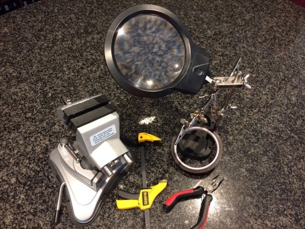
- Holding:
- Vise
- 3rd hand tool with magnifying glass
- Tape (preferably Kapton, but Scotch ok)
- Long/needle-nosed pliers
- Soldering:
- Soldering iron (preferably temp controlled solder station)
- Tip cleaner
- Rosin core solder
- Solder sucker or solder wick
- Cutting:
- Wire cutter (flush cut)
- Wire stripper
- Drilling:
- Drill
- 1/16″ bit (pilot for 9/64″)
- 9/64″ bit (standoffs)
- 11/64″ bit (pilot for 13/64″)
- 13/64″ bit (binding posts)
- 3/8″ Forstner bit (preferred – USB cable hole)
- Alternate: 1/8”, 3/16”, 7/32”, 1/4”, 9/32”, 5/16”, 11/32”, 3/8”, and 25/64” normal bits
- Other:
- Digital Multimeter (DMM)
- Small Phillips screwdriver
- 1.5V battery
- Sharpie
- Ruler
- Water spray bottle
Step 6: Manually Test the Relay Module
NOTE: the video above is for the 1-channel relay used for the PV module version. The process is basically the same for the 2-channel relay, but there are some minor differences.
This will confirm that your 2-channel relay module is the correct type (active-low trigger) and that it is functional.
- With Arduino powered off:
- Connect relay module GND to Arduino GND with female-to-male jumper___________
- Connect relay module VCC to Arduino 5V with female-to-male jumper ___________
- Connect female-to-male jumper to relay module IN1 (male end not connected) ___________
- Connect Arduino to laptop with USB cable:
- Arduino: green LED should be on ___________
- Arduino: yellow LED should be blinking once per second (assuming fresh-out-of box Arduino, running the default “Blink” sketch) ___________
- Relay module: no LEDs should be on ___________
- Relay module (K1 screw terminal): C (middle) terminal should have continuity with NC (bottom) terminal and no continuity with NO (top) terminal ___________
- Connect the male end of the jumper from the relay module IN1 pin to the GND socket near the blinking yellow LED on the Arduino ___________
- Relay module: should click and IN1 LED should come on ___________
- Relay module (K1 screw terminal): C (middle) terminal should have continuity with NO (top) terminal and no continuity with NC (bottom) terminal ___________
- Connect the male end of the jumper from the relay module IN1 pin to the “13” socket near the blinking yellow LED on the Arduino ___________
- Relay module: should click once per second ___________
- Relay module: IN1 LED should blink exactly opposite from the Arduino’s yellow LED ___________
NOTE: If your relay module behaves in the opposite manner to that described in each of the above three steps, that indicates that it is the wrong type, i.e. it has an active-high trigger instead of an active-low trigger. Your relay module may have a jumper that selects active-high/low, in which case you should change the jumper and try again. Otherwise, don’t despair – there is a configuration setting in the software Preferences that will allow you to use your active-high relay.
Repeat all of the above for the IN2 input and test the continuity on the screw terminal block K2.
Source: IV Swinger 2 – PCB (PV Cell, EMR)