Previously we have covered many types of Home automations using different technologies like DTMF Based Home Automation, PC Controlled Home Automation using Arduino, Bluetooth Controlled Home Automation. In this project, we are using IR based wireless communication for controlling home appliances. In this project, Arduino is used for controlling whole the process. We send some commands to the controlling system by using IR TV/DVD/MP3 remote for controlling AC home appliances. After receiving signal from IR remote, Arduino sends related signal to relays which are responsible for switching ON or OFF of the home appliances through a relay driver.
Working Explanation:
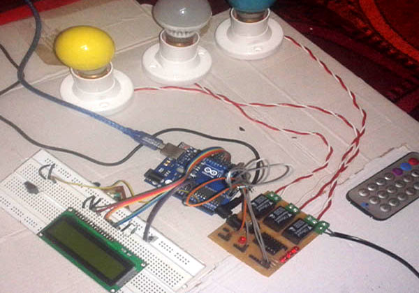
Working of this project is easily understandable. When we press any button of IR Remote then remote sends a code in form of train of encoded pulses using 38Khz modulating frequency. These pulses are received by TSOP1738 sensor and read by Arduino and then Arduino decodes received train of pulse into a hex value and compares that decoded value with the predefined hex value of the pressed button. If any match occurs then Arduino perform relative operation and the corresponding result is also displayed on 16×2 LCD by using appropriate commands. Here in this project we have used 3 bulbs of different colors, for demonstration which indicates Fan, Light and TV.
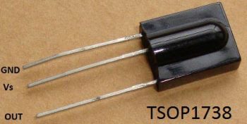
There are many types of IR Remote are available for different device but most of them are worked on around 38KHz Frequency signal. Here in this project we control home appliances using IR TV remote. For detecting IR remote signal, we use TSOP1738 IR Receiver. This TSOP1738 sensor can sense 38Khz Frequency signal. The working of IR remote and the TSOP1738 can be covered in detail in this article: IR Transmitter and Receiver
Components:
- Arduino UNO
- TSOP1738
- IR TV/DVD Remote
- ULN2003
- Relays 5 volt
- Bulb with holder
- Connecting wires
- Bread board
- 16×2 LCD
- Power supply
- PVT
- IC 7805
Here in this project we have used 7, 8 and 9 number button of IR remote, for controlling Fan, Light and TV respectively and ON/OFF button (Power button) is used for turning ON and OFF all the appliances simultaneously.
Here we have used toggle [EVEN ODD] method for ON and OFF the single home appliance. Toggle method is nothing but to get that whether the button is pressed even no of times or the odd no of times. This is found by getting the reminder after dividing it by 2 (i%2), if there is some reminder then device will be turned ON and if reminder is 0 then it will be turned OFF. Suppose Key 7 is pressed on the remote then remote sends a signal to Arduino through TSOP IR Receiver. Then Arduino decode it and store the decoded value into the results variable. Now results variable has a hex value 0x1FE00FF, after matching it with the predefined hex value of key 7 (see above image), Arduino turns ON the Fan. Now when we press the same key (key 7) again then IR sends the same code. Arduino gets same code and matched with same code like before but this time Fan turned OFF because of toggling the bit [EVEN ODD] (i%2).
Decoding IR Remote Control Signals using Arduino:
Here is a list of a DVD NEC type Remote decoded output codes: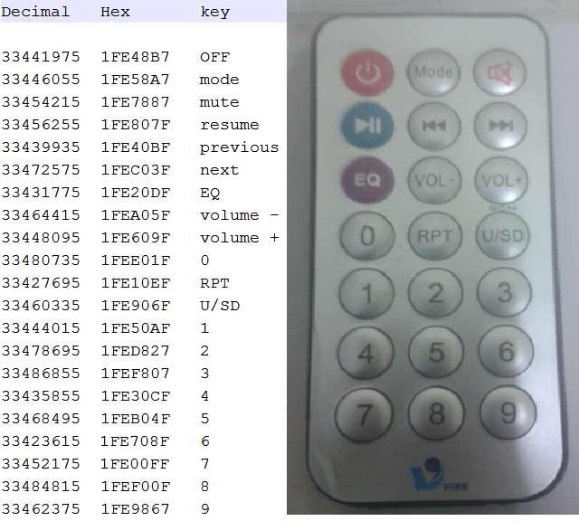
If you don’t know the Decoded output for your IR remote, it can be easily found, just follow these steps:
- Download the IR remote library from here https://github.com/z3t0/Arduino-IRremote.
- Unzip it, and place it in your Arduino ‘Libraries’ folder. Then rename the extracted folder to IRremote.
- Run the below program from your Arduino and open the Serial Monitor window in Arduino IDE. Now press any IR Remote button and see the corresponding decoded hex output in Serial Monitor window.
 * IRremote: IRrecvDemo - demonstrates receiving IR codes with IRrecv
 * An IR detector/demodulator must be connected to the input RECV_PIN.
 * Version 0.1 July, 2009
 * Copyright 2009 Ken Shirriff
 * http://arcfn.com
 */

#include <IRremote.h>
int RECV_PIN = 11;
IRrecv irrecv(RECV_PIN);
decode_results results;
void setup()
{
  Serial.begin(9600);
  irrecv.enableIRIn(); // Start the receiver
}
void loop() {
  if (irrecv.decode(&results)) {
    Serial.println(results.value, HEX);
    irrecv.resume(); // Receive the next value
  }
  delay(100);
}
The above program is taken from IRremote library’s ‘examples’ folder, you can check out more examples to learn more about using the IR remote. So that’s how we decoded the IR remote output.
Circuit Description:
Connections of this circuit is very simple here a liquid crystal display is used for displaying status of home appliances which is directly connected to arduino in 4-bit mode. Data pins of LCD namely RS, EN, D4, D5, D6, D7 are connected to arduino digital pin number 6, 7, 8, 9, 10, 11. And output pin of TSOP1738 is directly connected at digital pin number 14 (A) of Arduino. And Vcc pin is connected a +5 volt and GND pin connected at Ground terminal of circuit. A relay driver namely ULN2003 is also used for driving relays. 5 volt SPDT 3 relays are used for controlling LIGHT, FAN and TV. And relays are connected to arduino pin number 3, 4 and 5 through relay driver ULN2003 for controlling LIGHT, FAN and TV respectively.
Read More: IR Remote Controlled Home Automation using Arduino