Summary of iPod Information Screen using Arduino
This article details the creation of an iPod Information Screen using an Arduino to display track data and provide playback controls while driving. The author researched Apple's accessory protocols, utilized David Findlay's Arduino library for interfacing, and designed custom circuit boards. The project combines hardware components like a graphical LCD and push buttons with software libraries to create a user-friendly interface that displays song info, controls playback, and charges the device.
Parts used in the iPod Information Screen:
- Arduino (Pro Mini or UNO)
- PodBreakout
- Push Buttons (4x)
- Graphical LCD (MONOCHRON from Adafruit)
- 10k Potentiometer
- USB Mini Connector
- 3.5mm Audio Jack
- 100 Ohm Resistor
- 1k Ohm Resistor (3x)
- 1M Ohm Resistor (2x)
- 33k Ohm Resistor (2x)
- 22k Ohm Resistor
- 47k Ohm Resistor
- Male and Female Headers
- Wire
- Standoffs
- Enclosures
- Copper Clad Board
My girlfriend, a music buff, asked me to come up with a better way for her to look at the track information of the current song playing on her iPod touch while she was using it in the car. Those of you that have or have had an iPod touch know that it’s not the easiest thing to read while driving. To see the song information you have to double tap the home button and then still the text is extremely small.
My solution was to construct a device that would interface with the iPod and take the song information and then display it on a screen somewhere in the easy view of the driver. After quite a bit of work and research I finally arrived at the product you see here. My iPod information screen displays the song title, artist, album, song time, and play/pause symbol. It provides skip back, skip forward, and play/pause playback control as well as charges the iPod.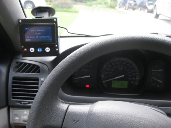
Step 1: The Research
The first step in making this device was to find out if it was even possible. I had never even really given interfacing with an iPod much thought before this and I had no idea if protocols publicly existed to do so.
One of the first websites I came across when researching was a Cornell senior design website that detailed the development of an iPod dock that took and sent commands to an iPod. The site, https://courses.cit.cornell.edu/ee476/FinalProjects/s2007/awr8_asl45/awr8_asl45/index.html, was very helpful in detailing the necessary connections, but most importantly it showed that this was in deed possible to do.
I came across several more resources, and then stumbled upon my primary resource. I found David Findlay’s blog, http://davidfindlay.org/weblog/files/2009_09_07_ipod_remote.php, and on it he talked about his development of an iPod remote and an Arduino library that handled all the iPod interfacing in a very simple way. This is the library I used in my project.
I also found this website useful outlining the Apple Accessory Protocol, https://nuxx.net/wiki/Apple_Accessory_Protocol. It’s not really necessary to understand as David’s library handles this behind the scenes, but I thought it was good to know and it may be useful for other applications.
Step 3: The Hardware
The connections that need to be made are detailed next to each pin on the website above. Also, the websites I’ve listed earlier in this Instructable talk about them too. I’m also going to touch on it.
Main
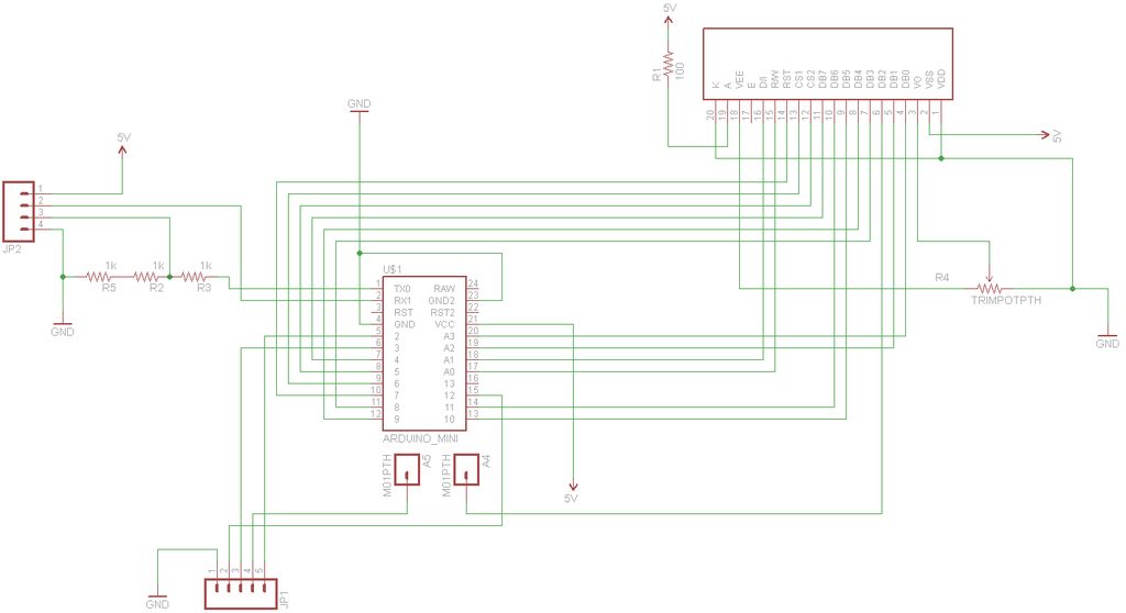
The LCD display uses the KS0108 chip popular to a lot of LCD displays. There is a library for the Arduino called GLCD. This takes most of the pins from the Arduino. For proper connections I’ll refer you to the documentation that comes with the library. A link to the library will be provided in the next step.
The serial transmit TX and receive RX, pins 1 and 0 respectively, go to the serial lines of the iPod. Be sure TX of the Arduino goes to RX of the iPod and vice-versa. That is, Arduino pin 1 to iPod connector pin 18 and Arduino pin 0 to iPod connector pin 19. Since the iPod operates at about 3V and the Arduino operates at 5V we need to use a voltage divider on the Arduino’s transmit line. That’s what the 1k Ohm resistors are for. Technically, I should be using a level shifter, but I found that it worked fine without it and the Arduino has no problem with receiving the incoming 3V data.
The remaining connections are for buttons.
Interface
Pin 21 of the iPod connector will be connected to ground through a 500k Ohm resistor, or in my case I used two 1M Ohm resistors in parallel. Connector pins 25 and 27 control how the iPod charges. If we put 2.8V on pin 25 and 2.0v on pin 27 we can get the iPod to draw about 1A and charge the battery. The is accomplished by simple voltage division as can be seen in the second schematic.
Other
All other connections are just straight connections. See the schematic and pinouts.
Step 4: The Software
- iPodSerial https://github.com/finsprings/arduinaap
- GLCD http://code.google.com/p/glcd-arduino/downloads/list
For how these are used I’ll refer you to the documentation that comes with each.
The code that actually runs the iPod Information Screen is attached below. I’m using the Advanced Remote as defined by the iPodSerial library. It handles translating user input from the buttons and putting information up on the screen, while the iPodSerial library handles talking to the iPod. I’m not going to go through the code here, but you can download it and take a look for yourself.
 iPodInfoSystem_v03.zip
Step 5: Designing the Boards
The circuit boards I made for this project are designed primarily for the to work with the enclosure system I designed. I made three separate boards. A main board that houses the Arduino and the LCD display, a button board that holds just the buttons, and and interface board that contains the resistors for charging and device recognition, etc.
The Parts
These are the major components I used to make the device:
- Arduino (I prototyped with an UNO, but used a Pro Mini for the final product)
- PodBreakout
- Push Buttons (4x)
- Graphical LCD (I used the MONOCHRON from Adafruit)
- 10k Potentiometer (for contrast)
- USB Mini Connector
- 3.5mm Audio Jack
- 100 Ohm Resistor
- 1k Ohm Resistor (3x)
- 1M Ohm Resistor (2x)
- 33k Ohm Resistor (2x)
- 22k Ohm Resistor
- 47k Ohm Resistor
For actually putting it all together, you’ll need:
- Male and Female Headers
- Wire
- Standoffs
- Enclosures
- Copper Clad Board (If you choose to etch your own boards)
For more detail: iPod Information Screen using Arduino
- How do I interface with an iPod using this project?
You can use David Findlay's blog and his Arduino library which handles the iPod interfacing simply. - What happens if I connect the Arduino TX directly to the iPod RX without modification?
The Arduino operates at 5V while the iPod uses 3V, so you must use a voltage divider with 1k Ohm resistors on the transmit line. - Can this device charge the iPod while displaying information?
Yes, by applying 2.8V to pin 25 and 2.0V to pin 27 via voltage division, the iPod draws about 1A to charge. - Which libraries are required to compile the code for this project?
You need the iPodSerial library and the GLCD library for the Arduino. - Does the LCD display show the current time of the song?
Yes, the screen displays the song title, artist, album, song time, and play/pause symbol. - What specific pins connect the Arduino serial lines to the iPod connector?
Arduino pin 1 connects to iPod connector pin 18, and Arduino pin 0 connects to iPod connector pin 19. - How is the contrast adjusted on the graphical LCD?
A 10k Potentiometer is used to adjust the contrast of the display. - What was the primary reason for creating this device?
The original text states the goal was to make it easier to read track information while driving since the iPod touch screen is small and hard to see.