Summary of IoT based health monitoring system | Arduino Project
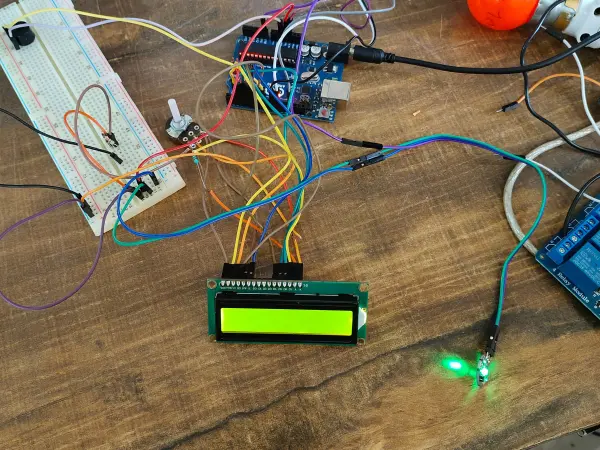
The article describes an IoT patient health monitoring system using an Arduino and a generic ESP8266 to read patient vitals (heart rate and body temperature), display them on an LCD, sound a buzzer on heartbeat, and upload data to ThingSpeak for remote monitoring.
Parts used in the IoT-based patient health monitoring system:
- Arduino (unspecified model)
- ESP8266 Wi-Fi module (generic)
- LiquidCrystal 16x2 LCD
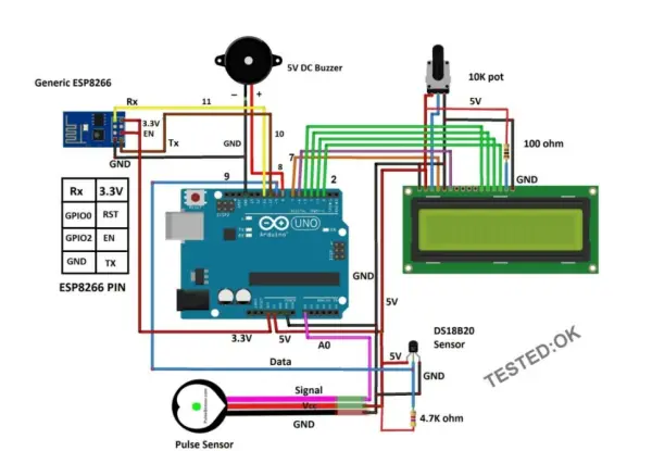
- SoftwareSerial library for serial communication (esp pins 10, 11)
- OneWire temperature sensor bus (pin 9)
- DallasTemperature sensor (DS18B20 or compatible)
- Pulse sensor (connected to A0)
- Buzzer (pin 8)
- Wires and power supply
- ThingSpeak service (channel ID and write API key)
An Arduino and a generic ESP8266 are utilized in an Internet of Things (IoT) patient health monitoring system. The project’s concept involves gathering and transmitting the health information of patients.
Project description
The term “IoT-based patient health monitoring system” refers to a broad category of medical devices that possess internet connectivity and are capable of measuring various health parameters of a patient who is connected to the device. These parameters may include heartbeat, body temperature, blood pressure, ECG, steps taken, and more. The equipment has the capability to record, transmit, and generate alerts in the event of any sudden changes in the patient’s health.
This definition encompasses a wide range of devices, ranging from smartwatches, fitness trackers, and smartphones to sophisticated and costly hospital equipment that can connect to the internet.
The purpose of an IoT-based health monitoring system is to facilitate remote monitoring of patients by healthcare professionals when the patient and the experts are located in different places. For instance, a patient can stay at home and continue with their daily activities while a doctor remotely monitors their health. Based on the received data, the healthcare expert can prescribe the most suitable treatment or take immediate action in case of an emergency.
Code
#include “ThingSpeak.h”
#include <ESP8266WiFi.h>
//——- WI-FI details ———-//
char ssid[] = “XXXXXXXXXXX”; // SSID here
char pass[] = “YYYYYYYYYYY”; // Passowrd here
//——————————–//
//———– Channel details —————-//
unsigned long Channel_ID = 123456; // Channel ID
const char * myWriteAPIKey = “ABCDEFG1234”; //Your write API key
//——————————————-//
const int Field_Number_1 = 1;
const int Field_Number_2 = 2;
String value = “”;
int value_1 = 0, value_2 = 0;
int x, y;
WiFiClient client;
void setup()
{
Serial.begin(115200);
WiFi.mode(WIFI_STA);
ThingSpeak.begin(client);
internet();
}
void loop()
{
internet();
if (Serial.available() > 0)
{
delay(100);
while (Serial.available() > 0)
{
value = Serial.readString();
if (value[0] == ‘*’)
{
if (value[5] == ‘#’)
{
value_1 = ((value[1] – 0x30) * 10 + (value[2] – 0x30));
value_2 = ((value[3] – 0x30) * 10 + (value[4] – 0x30));
}
else if (value[6] == ‘#’)
{
value_1 = ((value[1] – 0x30) * 100 + (value[2] – 0x30) * 10 + (value[3] – 0x30));
value_2 = ((value[4] – 0x30) * 10 + (value[5] – 0x30));
}
}
}
}
upload();
}
void internet()
{
if (WiFi.status() != WL_CONNECTED)
{
while (WiFi.status() != WL_CONNECTED)
{
WiFi.begin(ssid, pass);
delay(5000);
}
}
}
void upload()
{
ThingSpeak.writeField(Channel_ID, Field_Number_1, value_1, myWriteAPIKey);
delay(15000);
ThingSpeak.writeField(Channel_ID, Field_Number_2, value_2, myWriteAPIKey);
delay(15000);
value = “”;
}
Code for Arduino
#include <LiquidCrystal.h>
#include <SoftwareSerial.h>
#include <OneWire.h>
#include <DallasTemperature.h>
#define USE_ARDUINO_INTERRUPTS true
#include <PulseSensorPlayground.h>
SoftwareSerial esp(10, 11);
LiquidCrystal lcd(7, 6, 5, 4, 3, 2);
#define ONE_WIRE_BUS 9
#define TEMPERATURE_PRECISION 12
OneWire oneWire(ONE_WIRE_BUS);
DallasTemperature sensors(&oneWire);
DeviceAddress tempDeviceAddress;
int numberOfDevices, temp, buzzer = 8;
const int PulseWire = A0;
int myBPM, Threshold = 550;
PulseSensorPlayground pulseSensor;
unsigned long previousMillis = 0;
const long interval = 5000;
void setup()
{
lcd.begin(16, 2);
Serial.begin(9600);
esp.begin(115200);
sensors.begin();
numberOfDevices = sensors.getDeviceCount();
pulseSensor.analogInput(PulseWire);
pulseSensor.setThreshold(Threshold);
pulseSensor.begin();
pinMode(buzzer, OUTPUT);
digitalWrite(buzzer, HIGH);
lcd.setCursor(0, 0);
lcd.print(” IoT Patient”);
lcd.setCursor(0, 1);
lcd.print(” Monitor System”);
delay(1500);
digitalWrite(buzzer, LOW);
lcd.clear();
}
void loop()
{
myBPM = pulseSensor.getBeatsPerMinute();
if (pulseSensor.sawStartOfBeat())
{
beep();
lcd.setCursor(0, 1);
lcd.print(“HEART:”);
lcd.print(myBPM);
lcd.setCursor(9, 1);
lcd.print(” BPM”);
delay(20);
}
sensors.requestTemperatures();
for (int i = 0; i < numberOfDevices; i++)
{
if (sensors.getAddress(tempDeviceAddress, i))
{
temp = printTemperature(tempDeviceAddress);
lcd.setCursor(0, 0);
lcd.print(“BODY:”);
lcd.print(temp);
lcd.print(” *C”);
}
}
upload();
}
int printTemperature(DeviceAddress deviceAddress)
{
int tempC = sensors.getTempC(deviceAddress);
return tempC;
}
void beep()
{
digitalWrite(buzzer, HIGH);
delay(150);
digitalWrite(buzzer, LOW);
}
void upload()
{
unsigned long currentMillis = millis();
if (currentMillis – previousMillis >= interval)
{
previousMillis = currentMillis;
esp.print(‘*’);
esp.print(myBPM);
esp.print(temp);
esp.println(‘#’);
}
}
- What microcontrollers are used in the project?
An Arduino and a generic ESP8266 are used. - How are heart rate and temperature measured?
Heart rate is measured with a pulse sensor on analog pin A0 and temperature is measured with a DallasTemperature sensor on a OneWire bus (pin 9). - How is patient data displayed locally?
Data is displayed on a 16x2 LiquidCrystal LCD. - How is data transmitted to the cloud?
The ESP8266 connects to Wi-Fi and uses ThingSpeak.writeField to upload fields to a ThingSpeak channel. - How often does the Arduino send data to the ESP8266?
The Arduino sends concatenated data (with * prefix and # suffix) every 5 seconds based on a 5000 ms interval. - How does the ESP8266 parse incoming serial data?
It reads serial strings framed with * and #, extracts digit characters to form two numeric values, and uploads them as two ThingSpeak fields. - What indicates a heartbeat locally?
A buzzer is briefly activated when the pulse sensor detects the start of a beat. - What Wi-Fi details are required?
The SSID and password must be provided in the ESP8266 code variables ssid and pass. - What cloud credentials are required for ThingSpeak?
The ThingSpeak channel ID and the write API key must be set in the ESP8266 code variables Channel_ID and myWriteAPIKey.