Summary of Introduction to Arduino: A Versatile Physical Computing Platform
Arduino Interfacing enables interaction with the physical world via sensors and actuators using affordable open-source microcontroller boards. It covers board features (analog/digital ports, ATmega328 specs), power options, serial communication, typical first Blink program, sensor calibration and physics testing, and robotics with RedBot (motors, line-following IR sensors, accelerometer) including RedBot library usage and examples. Basics of LEDs, p-n junctions, and current-voltage behavior are explained, emphasizing correct orientation and using resistors to limit voltage/current for safe operation.
Parts used in the Arduino Interfacing Project:
- Arduino board (e.g., Arduino UNO with ATmega328)
- USB cable
- Batteries (optional power source)
- LEDs
- Resistors
- RedBot robotic platform
- Two gear motors (for RedBot)
- Line follower IR sensors
- Accelerometer (RedBotAccel)
- RedBot library (software)
Arduino Interfacing
Introduction to Arduino: Arduino serves as a medium for engaging with the physical world through sensors. It constitutes an open-source physical computing platform centered around a straightforward and affordable micro-controller board, accompanied by a development environment tailored for writing software compatible with the board. As an open-source electronics prototyping platform, Arduino facilitates the creation of interactive objects that respond to inputs from diverse switches or sensors while managing outputs like LED lights, motors, and other physical elements. Arduino projects can either function as stand-alone entities or seamlessly communicate with software running on your computer.
To power the Arduino micro-controller, one can utilize either the USB cord or batteries, providing flexibility in its applications.
Microcrontroller
The Arduino microcontroller is equipped with 6 analog input ports and 13 digital ports, which can function as either inputs or outputs. It encompasses several key components, including a microprocessor, RAM, flash memory, a clock (oscillator), and an A/D (analog to digital) converter. All these components are integrated into a compact chip, serving as the core of the Arduino board. For instance, the widely used ATmega328 chip boasts 2 kB of RAM, 32 kB of programmable Flash memory, a 20 MHz oscillator clock, and 32 pins. Remarkably, this microcontroller is remarkably cost-effective, with a price of less than USD 1.50, particularly when purchased in high volume.
Arduino offers a diverse range of boards, each with its unique configuration. These boards come equipped with USB connectivity, built-in LEDs, power jack connections, and distinct pins designated for both inputs and outputs. Moreover, users have the option to enhance the board’s capabilities by utilizing shields, which enable additional functionalities such as wifi connectivity, GPS support, stepper motor control, and more.
Arduino finds extensive use in prototyping and serves as a fundamental component in numerous Kickstarter projects. In recent times, its application has expanded to include educational and teaching projects as well (Esposito et al., 2015).
First Arduino Program
Typically, the initial program to run is the “Blink” program, designed to make an LED flash at a specified rate. The simplest version of this program utilizes one of the LEDs integrated directly into the Arduino UNO board, specifically controlled via pin 13.
To begin, establish a connection between the Arduino board and the computer using the USB cable. Next, launch the Arduino software and compile the “Blink” program. It is crucial to choose the correct “Serial Port” for communication. This can be done by navigating to the “Tools” menu, selecting “Serial Port,” and then choosing the appropriate “USB” port (refer to Fig.@ for guidance). Additionally, you may need to set the Board type, also found in the “Tools” menu. Once the setup is complete, you can transfer the program to the Arduino board by clicking the “right arrow” button located at the top left of the program (see Fig.@ for reference).
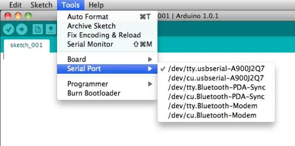
Choose the USB port from the available Serial Ports options, as this informs the Arduino program where to send the compiled program.
Serial Communication
The Arduino features a built-in library that facilitates serial communication with a computer. This allows the Arduino board to send messages back to the computer. To initialize the serial communication, the command “Serial.begin(9600);” is used in the setup() function. Sending numerical data or text to the computer can be achieved using the command “Serial.println(voltage);,” where ‘voltage’ represents the measured voltage, for instance. It is essential to use the correct quotation marks when sending text, as the compiler is particular about it. Moreover, in the Arduino C script, each line must be terminated with a semicolon.
Sensors and Physics
Arduino projects encompass two fundamental aspects. Firstly, the engineering aspect involves integrating sensors, such as the temperature sensor, and processing the electrical signals according to the manufacturer’s specifications. This part focuses on the technical implementation and functionality of the sensors.
Secondly, the physics aspect delves into testing the limits of the sensors and seeking answers to various questions, such as the sensor’s resolution, response time, and specific heat. The objective here is to calibrate and evaluate the sensor’s accuracy. To achieve this, each question is approached with a hypothesis, and a strategic plan for testing is developed. Through this process, quantitative assessments of the sensor properties are obtained, enabling comparisons with published specifications and the generation of additional findings.
Bot
A bot like SparkFun’s RedBot operates as a robotic platform that relies on sensors to control its movement. The Arduino microcontroller processes the sensor inputs and issues commands to the motor. The bot is equipped with two gear motors, each capable of producing approximately 0.078Nm of torque, which enable the motion of the 3-wheel vehicle. By adjusting the speed of these motors, the bot’s steering can be controlled effectively.
To navigate its environment, the bot employs sensors. One such sensor is the line follower, which measures the amount of reflected infrared light and detects changes from dark to light on the surface. Proper mounting of this sensor is critical, with a recommended distance of about 3mm from the surface. It comes with three connecting wires – GND, VCC, and OUT – which are connected to the 5V potential difference from the Arduino.
Furthermore, the bot features an accelerometer, which is responsible for detecting any impacts with other objects or sudden vibrations, aiding in its ability to avoid obstacles and follow a designated path.
Facilitating a more straightforward programming experience, the RedBot is complemented by the readily available RedBot library, complete with comprehensive documentation. The library incorporates three classes of objects, enhancing the versatility and functionality of the RedBot platform.
- RedBotAccel
- RedBotMotor
- RedBotSensor
After successfully including the library using “#include <RedBot.h>”, you gain access to its functions. You can utilize functions like “drive(int speed)”, “stop()”, “brake()”, “leftDrive(int speed)”, and “rightDrive(int speed)”, where ‘speed’ is an integer ranging from -255 to 255. By inputting a negative value, you can prompt the motor to move in reverse.
#include <RedBot.h> // This line “includes” the RedBot library into your sketch.
// Provides special objects, methods, and functions for the RedBot.
RedBotMotors motors; // Instantiate the motor control object. This only needs
// to be done once.
void setup()
{
motors.drive(255); // Turn on Left and right motors at full speed forward.
delay(2000); // Waits for 2 seconds
motors.stop(); // Stops both motors
delay(5000);
// pivot — spinning both motors CCW causes the RedBot to turn to the right
motors.rightMotor(-100); // Turn CCW at motorPower of 100
motors.leftMotor(-100); // Turn CCW at motorPower of 100
delay(500); // for 500 ms.
motors.brake(); // brake() motors
delay(500); // for 500 ms.
}
void loop()
{
}
In addition to its functions, the library encompasses various examples, including BasicTest, DriveForward, and LineFollowing_IRSensors. Below is a snippet from the LineFollowing Sensors example:
#include <RedBot.h>
RedBotSensor IRSensor1 = RedBotSensor(A3); // initialize a sensor object on A3
RedBotSensor IRSensor2 = RedBotSensor(A6); // initialize a sensor object on A6
RedBotSensor IRSensor3 = RedBotSensor(A7); // initialize a sensor object on A7
void setup()
{
Serial.begin(9600);
Serial.println(“Welcome to experiment 6!”);
Serial.println(“————————“);
}
void loop()
{
Serial.print(“IR Sensor Readings: “);
Serial.print(IRSensor1.read());
Serial.print(“\t”); // tab character
Serial.print(IRSensor2.read());
Serial.print(“\t”); // tab character
Serial.print(IRSensor3.read());
Serial.println();
delay(100);
}
Light Emitting Diodes
Light-emitting diodes, commonly known as LEDs, operate based on two semiconductors with distinct properties. One of the semiconductors is p-type, while the other is n-type. The charge carriers in the p-type material are known as holes, while in the n-type material, they are electrons. Each semiconductor possesses a characteristic band gap, which represents the forbidden energy region for electrons. When a p-n junction is formed, current flows effortlessly in one direction but is blocked in the opposite direction. At this junction, electrons and holes tend to recombine, resulting in the emission of light.
As a consequence of the junction’s asymmetry, the LED possesses a cathode and anode, or a positive and negative leg. Hence, the orientation in which the LED is connected becomes significant. One of the legs is longer (anode) and represents the positive end.
The applied voltage for light emission varies depending on the wavelength of the emitted light. Typical values can range from around 1.8V for red light to approximately 3.3V for blue light. If the voltage applied is too low, recombination will not occur adequately, resulting in no light emission. On the other hand, if the voltage is too high, it can damage the LED. Unlike ohmic resistors, where the current increases linearly with voltage, in semiconductors, the current increases exponentially with voltage. Therefore, applying even a slightly higher voltage can lead to a significant current surge that may quickly damage the narrow gap in the LED.
The current-voltage behavior of a diode, including an LED, can usually be represented by the following equation:
The current-voltage behavior of a diode, including an LED, can be described using the following equation, where kB represents the Boltzmann constant, T denotes the temperature, and q represents the charge of the carrier.
Since the Arduino board typically supplies 5V, a direct connection to the red LED is not possible as it requires a reduced voltage. To achieve this, a resistor is added to the circuit. When connected, part of the voltage drop will occur across the resistor. For instance, when connecting a red LED, a resistor with a voltage drop of 3.2V is selected, so that the remaining 1.8V voltage drop occurs across the LED.
- How do you power the Arduino?
You can power the Arduino using the USB cord or batteries as stated in the article. - What is the typical first Arduino program?
The typical first program is the Blink program to flash an LED at a set rate using pin 13. - How do you start serial communication with Arduino?
Initialize serial communication with Serial.begin(9600); in the setup() function. - Can Arduino boards be expanded with additional functionality?
Yes, boards can be enhanced using shields for features like wifi, GPS, or stepper motor control. - What sensors does the RedBot use for navigation?
RedBot uses line follower IR sensors and an accelerometer to detect reflections and impacts or vibrations. - How are RedBot motors controlled via the library?
Using the RedBot library functions such as drive(int speed), stop(), brake(), leftDrive(int speed), and rightDrive(int speed) with speed values from -255 to 255. - What is important when mounting the line follower sensor?
The sensor should be mounted about 3mm from the surface for proper detection. - Why is a resistor used with an LED on Arduino?
A resistor drops part of the voltage so the LED receives the correct voltage and current to prevent damage. - What determines the LED forward voltage?
The forward voltage depends on wavelength, typically around 1.8V for red and about 3.3V for blue, as noted in the article.