Summary of Interfacing an Arduino with LCDs
This article details interfacing an Arduino with a 16x2 character LCD and a 128x64 graphic LCD. It covers wiring, library usage (LiquidCrystal and KS0108), and demonstrates static text, scrolling ticker tape, and animated bitmap display techniques using flash memory storage.
Parts used in the Arduino LCD Project:
- Arduino hardware platform
- 16x2 character LCD
- 128x64 Graphic LCD
- LiquidCrystal Library
- KS0108 Graphics LCD library
- Win32 C/C++ environment for algorithm testing
Introduction
This is the second article in a three part series I am writing on the Arduino hardware platform. This article focuses on wiring an Arduino to a character LCD and a graphic LCD, and includes static and animated demos to show off the capabilities of each display.
Character and Graphic LCDs
After I initially discovered the Arduino platform, I immediately noticed a wide variety of components that can be connected to an Arduino – everything from inexpensive LEDs, to a moderately priced Ethernet shield, to an outrageous and over-the-top tank shield (which sells for nearly $200!). While shopping for my Arduino, I noticed that LCDs were fairly inexpensive so I purchased a $10 16×2 character LCD, and an $18 128×64 Graphic LCD.
Character LCDs and graphic LCDs are completely different devices and require different libraries and APIs to drive them. Fortunately, both devices are supported by the Arduino community. For my character LCD, I used the LiquidCrystal Library, and for my graphic LCD, I used the KS0108 Graphics LCD library.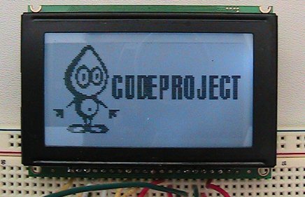
Character LCD
Connecting a character LCD and programming it was a breeze and I didn’t run into any problems. I simply followed the instructions and wiring diagram in the Arduino Character LCD Tutorial and everything worked as expected. After running the LCD_example sample sketch, I wrote a sketch to take advantage of my character LCD called HelloCodeProject:
/*
    HelloCodeProject.cpp, based off of LCD_example from
    http://www.hacktronics.com/Tutorials/arduino-character-lcd-tutorial.html
*/

#include <LiquidCrystal.h>

const int BACK_LIGHT = 13;          // Pin 13 will control the backlight

// Connections:
// RS (LCD pin 4) to Arduino pin 12
// RW (LCD pin 5) to Arduino pin 11
// Enable (LCD pin 6) to Arduino pin 10
// LCD pin 15 to Arduino pin 13
// LCD pins d4, d5, d6, d7 to Arduino pins 5, 4, 3, 2
LiquidCrystal g_lcd(12, 11, 10, 5, 4, 3, 2);

void setup()
{
    pinMode(BACK_LIGHT, OUTPUT);
    digitalWrite(BACK_LIGHT, HIGH);     // Turn backlight on.
                // Replace 'HIGH' with 'LOW' to turn it off.
    g_lcd.clear();                      // Start with a blank screen
    g_lcd.setCursor(0, 0);              // Set the cursor to the beginning
    g_lcd.print("Hello,");
    g_lcd.setCursor(0, 1);              // Set the cursor to the next row
    g_lcd.print("CodeProject");
}

void loop()
{
}
TickerTape
The second sketch I wrote was TickerTape, which simulates a ticker tape message scrolling across the display. Since TickerTape was the first sketch that I wrote which used an algorithm (the algorithm uses a single buffer for the message, an int to keep track of the starting point of the message to display, and takes into consideration when the message ‘wraps’ around the end of the buffer), I decided to code the algorithm in a native Win32 C/C++ application first. Since the Arduino has only limited debugging capabilities, I felt that coding the algorithm first in an environment which supports line level debugging and breakpoints would be faster than trying to debug within the Arduino using a bunch of Serial.println() statements. After I verified that the algorithm worked, I coded up the TickerTape sketch:
/*
    TickerTape.cpp, based off of LCD_example from
    http://www.hacktronics.com/Tutorials/arduino-character-lcd-tutorial.html
*/

#include <LiquidCrystal.h>

const int BACK_LIGHT = 13;          // Pin 13 will control the backlight
const char* MESSAGE = "Example 2: Hello, CodeProject. ";
const int MESSAGE_LENGTH = 31;
const int DISPLAY_WIDTH = 16;

// Connections:
// RS (LCD pin 4) to Arduino pin 12
// RW (LCD pin 5) to Arduino pin 11
// Enable (LCD pin 6) to Arduino pin 10
// LCD pin 15 to Arduino pin 13
// LCD pins d4, d5, d6, d7 to Arduino pins 5, 4, 3, 2
LiquidCrystal g_lcd(12, 11, 10, 5, 4, 3, 2);

void setup()
{
    pinMode(BACK_LIGHT, OUTPUT);
    digitalWrite(BACK_LIGHT, HIGH);     // Turn backlight on.
                        // Replace 'HIGH' with 'LOW' to turn it off.
    g_lcd.clear();                      // Start with a blank screen
    Serial.begin(9600);
}

void loop()
{
    static int s_nPosition = 0;
    int i;
    if(s_nPosition < (MESSAGE_LENGTH - DISPLAY_WIDTH))
    {
        for(i=0; i<DISPLAY_WIDTH; i++)
        {
            g_lcd.setCursor(i, 0);
            g_lcd.print(MESSAGE[s_nPosition + i]);
        }
    }
    else
    {
        int nChars = MESSAGE_LENGTH - s_nPosition;
        for(i=0; i<nChars; i++)
        {
            g_lcd.setCursor(i, 0);
            g_lcd.print(MESSAGE[s_nPosition + i]);
        }

        for(i=0; i<(DISPLAY_WIDTH - nChars); i++)
        {
            g_lcd.setCursor(nChars + i, 0);
            g_lcd.print(MESSAGE[i]);
        }
    }

    s_nPosition++;
    if(s_nPosition >= MESSAGE_LENGTH)
    {
        s_nPosition = 0;
    }

    delay(500);
}
My second attempt compressed the image by using run length encoding. Since much of the image’s pixels repeat, I thought this might be an efficient way to reduce the data needed for the image. The format of each line was:
[1,0,-42], run1, run2, ..., runN, -1
The first int is a marker. 1 indicates the first run of the line is black, 0 indicates the first run of the line is white, and -42 indicates the array is finished. The second int indicates the run length and toggles back and forth between black and white until -1 is found, which indicates the end of the row. As an example, if there was:
1, 64, 32, 32, -1
…64 black pixels would be drawn, then 32 white pixels, then 32 black pixels.
This worked better as the sketch size was now small enough to upload to the Arduino, however the array was too large for the Arduino’s stack. When I included the entire array, the Arduino crashed and it kept restarting itself over and over, and I found that if I included only 1/4 of the total array it worked fine, so the RLE approach didn’t work either.
After doing some investigation, I discovered that large amounts of data need to be stored in flash memory using the PROGMEM keyword. Using PROGMEM, the raw array is declared as:
static prog_uchar bits[] PROGMEM = {
Data is then read from flash memory via pgm_read_byte_near():
char val = pgm_read_byte_near(bits + (i + (128 * j)));
…and then drawn one pixel at a time via GLCD.SetDot().
In addition to discovering that I needed to store the data in flash memory, I also learned that the beta version of the KS0108 library also included a new function, DrawBitmap(). The second version of CodeProjectLogo (just comment out the #define USE_SET_DOT statement) declares the array as:
…and draws the bitmap via GLCD.DrawBitmap()
For more detail: Interfacing an Arduino with LCDs
- What libraries are required for character and graphic LCDs?
The LiquidCrystal Library is used for the character LCD, while the KS0108 Graphics LCD library is used for the graphic LCD. - How can I control the backlight on the character LCD?
Connect LCD pin 15 to Arduino pin 13 and use digitalWrite to set it HIGH or LOW. - Why did the author write the TickerTape algorithm in C/C++ first?
The author needed line level debugging and breakpoints which were not available in the Arduino environment. - What issue occurred when storing large image arrays directly?
The array was too large for the Arduino's stack, causing the device to crash and restart repeatedly. - How should large amounts of data be stored on the Arduino?
Data must be stored in flash memory using the PROGMEM keyword. - Which function allows reading data from flash memory?
The pgm_read_byte_near function is used to read data from flash memory byte by byte. - What new function was found in the beta version of the KS0108 library?
The beta version included a new DrawBitmap function. - How does run length encoding format represent pixel runs?
The format starts with a marker integer indicating color, followed by run lengths that toggle between black and white until -1 is found.