Project Goal
The goal of this project is to create a low resolution display of graphical art that interacts with people who are handling it. My basic idea is to create such a “magic box” with a LED matrix on one side. It should be small enough that it can be held by hands. Also, it has to work independently from a computer, so that it be carried around. “(It will be best if the series of graphics generated by the user can be stored somewhere.)”
The basic design of input and output are the following:
- Input
- amount of tilt
- frequency of vibration (optional)
- Output
a low resolution display made of LED lights that refreshes constantly - Processing
- Store amount of tiltation and vibration(optional) in a data structure
- Visualize the data by controlling the intensity of individual LEDs.
Schematics
- single-color LED matrix with MAX72XX Driver
- dual-color LED matrix with 2 MAX72XX Drivers
- accelerometer
Hardware List
LED matrix
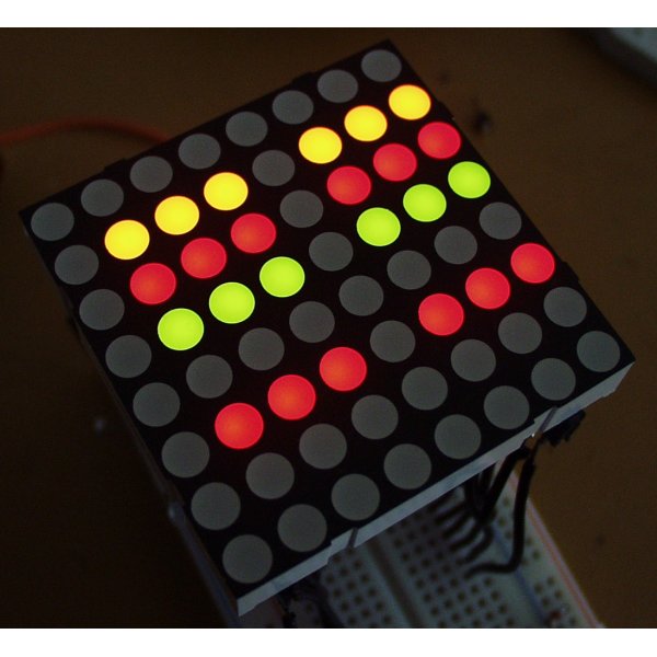
- 8×8 LED matrix display
8×8 RG LED matrix
I found one with dual-color(red and green) LEDs ($4.5). With different intensity, we may get a range of pleasant colors including orange and yellow. The matrix height is 3.2in, which is the biggest among other 8×8 LED matrices with reasonable price that I could find.
LED Dot Matrix Display Red/Green #LTP2188AA LiteON
- LED display driver
LED display drivers lets you control individual LEDs easier. My two choices are either MAX7219 or MAX7221($7.02 a piece). They can drive either 64 individual Led’s, or up to 8 digits of 7-segment displays. The big advantage of these drivers are that they can be controlled from the Arduino using only 3 of the digital output pins. There are also examples on driving a dual-color matrix using 2 such drivers. On the other hand, the limitation is that I couldn’t use PWM(Pulse Width Modulation) to control the intensity of individual LEDs. For the dual-color LED, with PWM, I could virtually get 255*255 colors; I can only set 4 states: off, R,G,RG without PWM.
Most Arduino projects uses MAX7219 and MAX7221 interchangeable, while I think in my case MAX7221 would work better because of the following reason:
“The MAX7221 was designed for reduced electromagnetic interference (EMI). EMI could lead to some jitter in the readings from the analog inputs of the Arduino or if the Led matrix is placed near some audio circuit it can introduce audible noise to the signal. So, if your project would go into categories like : audio gadget, audio levelmeter, (low-)voltage measurement, etc. than better take the MAX7221. “[4]
Since my project also has analog input to sense acceleration, I’m afraid that EMI may prevent me from getting correct input from the accelerometer. MAX7219, MAX7221: Serially Interfaced, 8-Digit, LED Display Drivers
Accelerometer
ADXL32X accelerometer with breakout board
We can use the accelerometer’s ability of sensing acceleration to measure a variety of things, such as acceleration (of course!), tilt angle, incline, rotation, vibration, collision detection, and gravity. In my project, I will mainly use the accelerometer to measure tilt angle.
My first choice is ADXL322, a dual-axis accelerometer (measures acceleration along x and y coordinates) with sensoring ange from -2g to 2g and analog output 0-5V. It costs about $7.95 a piece. SparkFun also sales ADXL322 breakout board. The breakout board will save a lot of wiring effort, however, it will cost $29.95, 3 times as pricy as the accelerometer alone.
Approximate Cost
- accelerometer: $7.95
- LED matrix: $4.5
- LED driver: $7.04
Total: $19.49 (shipping not included)
Resource
Schematics
Hardware
Schematics
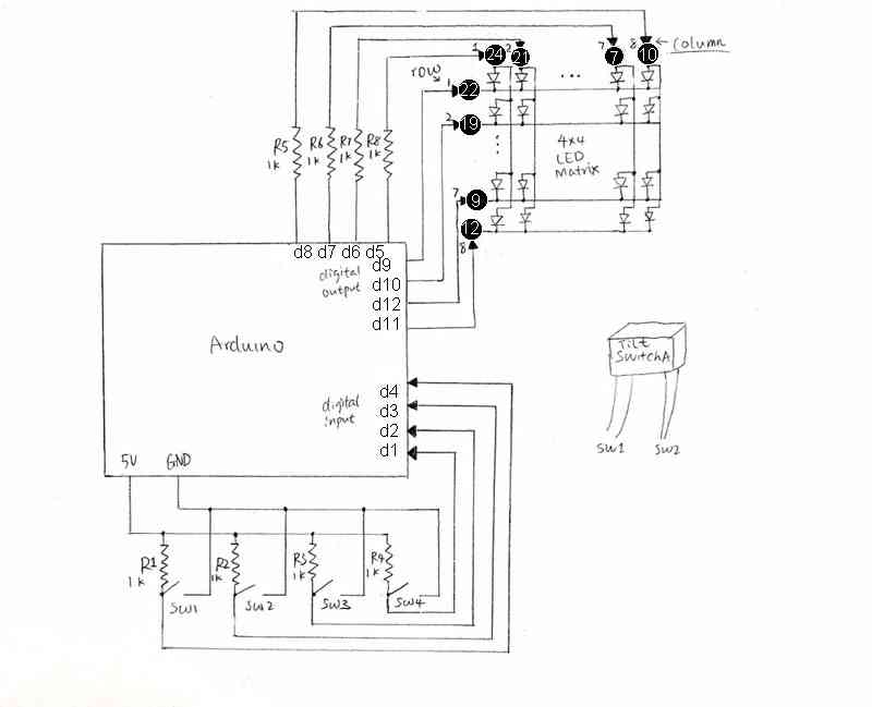
The following schematic diagram shows input/output connections from Arduino to two tilt switches and one 8*8 Green/Red LED matrix. To start with the simplest case, I will treat the LED matrix as 4*4 with single color (only use 16 green LEDs at the 4 corners of the matrix).
Notes:
- Each tilt switch has 4 output wires, so that it acts as 2 switches. SW1 and SW2 are associated with tilt switch A, and SW3 and SW4 are associated with tilt switch B.
- The inputs for LED matrix are labeled by their pin number(circled). Column and row numbers are also shown in the schematics.
- Resistors used in this schematics are chosen to be 1kOhms based on approximation. During prototyping, I may try resistors of different resistances to maximize the performance of my project.
Software
Overview
The arduino will read inputs from the 4 switches, and turn on a certain group of LEDs based on the state of the 4 switches.
The assembly program will constantly read the status of the 4 pins that are connected to the switches, and copy the status into a reserved space in memory every tenth of a second (or other interval of time). For example:
0 0 0 1        //PIN 1,2,3 LOW; PIN 4 HIGH
1 0 1 0
0 0 0 0
0 0 1 1
0 0 1 1
0 0 1 1
0 0 1 1
0 0 1 1
0 0 0 1
...
In this way, the program can remember past status. If the status doesn’t change for about 10 seconds, the program will send the last 100 status from memory one after another to the arduino, which modifies the value of the 4 input pins. Then the arduino is able to ‘playback’ the LED interaction generated by the user.
Concerns:
- The LED will not be ‘responding’ to any movement during playback. Ideally it should stop playback once the switches change status.
- Consider the random output we get when reading pin status in Lab7(Every time we send r d, the buffer changes randomly unless we give a constant signal to the pins, such as connecting them to ground or power), I think it’s a bad idea to switch pins between input/output mode in arduino_loop.pde. Therefore, I will change the writePin and readPin method so that they only modify the variables that contain the pin status without utilizing any hardware.
Arduino
communication
The arduino program will be based on arduino-loop.pde, which uses a loop to constantly response to commands from the PC, such as “w d 13 1”, or “r d”.
Modifications to this part will be:
- When receiving the “r d” command, it only prints to serial port the status of 4 pins, instead of 12 pins.
- When receiving commands like “w d 13 1”, instead of writing HIGH to pin 13, it modifies the variable that contains the status of pin 13. (I cannot write to pin 13 directly, which is an input pin for reading switch status.)
interaction with LED
This will be in the same loop as the communication. For testing purposes, I will reuse the code from the sketch I wrote for hardware testing: turn a row of LEDs on or off base on the status of the switch. This is simple but enough to create a series of patterns that will be regenerated later. Since priority is given to the assembly part, I will only implement the artistic side of the LED controls as time allows.
preventing conflict between assembly and arduino
When arduino is replaying past status, the LEDs shouldn’t respond to motion. Therefore, I will add one more operation “p” , which alters the value of a boolean variable. The code for reading from the 4 input pins will be executed only if this boolean variable is false.
C Driver
Arduino-serial.c will be used to connect the assembly to Arduino. The only change will be not printing the content of buffer to screen when “r” option used.
Assembly
In an endless loop with a short delay in every cycle:
- send “r d” and call read_until.
- copy the pin status (in the format of 4 characters ending with a 0) from the C buffer to a reserved array in memory.
- update the index pointer to the next available byte: To prevent array out of bound, when this pointer reaches end of array, it will be reseted to the beginning, so newer status can overwrite the older status.
- test for continuous repeated entries: Make a counter for number of continuous occurrence of the same status. Then test wether the current status is the same with the previous one. If so, increment the counter. Otherwise, reset the counter to 0. When the counter reaches 100(about 10 seconds),it will call the “playback” function and reset to 0.
Playback function:
- send “p” option to stop Arduino from responding to motion.
- enter a secondary loop that send past status to arduino: The loop will run about 100 times. The index pointer will jumps back in memory and start go through each set of status, translate into commands (i.e. “d w # #”) and copy to C buffer. I will also take into consideration when there are not enough status to go go back, and when the pointer is wrapped around 0.
- send “p” again to enable Arduino for responding to motion.
For more detail: Interactive LED box Using Arduino