Summary of Step by Step Guide to the Arduino Leonardo
The Arduino Leonardo is a new board featuring the ATmega32U4 chip with built-in USB, offering 18 digital pins and 7 PWM pins. This guide details pin mappings for the four extra digital pins (D14-D17) and explains the new timer configurations for the additional PWM capabilities compared to the Uno.
Parts used in the Arduino Leonardo:
- ATmega32U4 chip
- Built-in USB
- Digital pins D0-D17
- ICSP header
- Rx LED
- Via attached to Rx LED
- Timer0
- Timer1
- Timer3
- Timer4
The Arduino team is now shipping their latest creation – the Leonardo. It is the first Arduino to use Atmel’s ATmegaXU4 series chip with built-in USB. This change is big and it has big benefits. In addition to the built-in USB, it offers more digital and analog pins. This step by step guide gives you the details you need to know to start using it.
For a more comprehensive guide, see my article – Arduino Leonardo versus Uno – What’s New.
Step 1: More Digital Pins
There are four more digital pins. The Uno has 14 digital pins: D0-D13. The Leonardo has 18: D0-D17. The extra pins have been mapped to the ICSP header. Their mappings are:
- D14 – MISO – PB3
- D15 – SCK – PB1
- D16 – MOSI – PB2
- D17 – SS – PB0
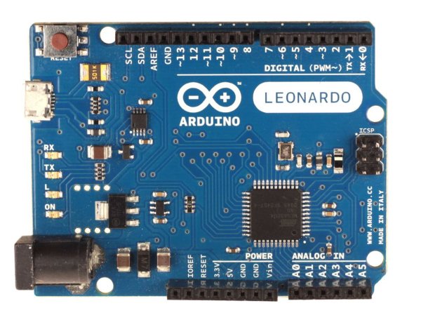
Pin D17 (SS) does not have a corresponding pin on the ICSP header, nor anywhere on the board. In order to use it, you must solder a wire to either the end of the Rx LED or the via attached to it – see photo.
Step 2: Extra PWM pin
The Leonardo has 7 PWM pins instead of 6. ATmega32U4 also has a new timer, timer4 which has 10 bits and uses a PLL to count at 64MHz. Their mappings are different as well:
- D3: 8-bit timer0
- D5: 16-bit timer1&3
- D6: 10-bit timer4
- D9: 16-bit timer1&3
- D10: 16-bit timer1&3
- D11: 8-bit timer0
- D13: 10-bit timer4
For more detail: Step by Step Guide to the Arduino Leonardo
- What is the main difference between the Arduino Uno and Leonardo?
The Leonardo uses the ATmega32U4 chip with built-in USB, offers more digital and analog pins, and has different timer mappings. - How many digital pins does the Arduino Leonardo have?
The Arduino Leonardo has 18 digital pins, ranging from D0 to D17. - How can I use pin D17 on the Arduino Leonardo?
You must solder a wire to either the end of the Rx LED or the via attached to it because D17 has no corresponding pin on the ICSP header. - Does the Arduino Leonardo have more PWM pins than the Uno?
Yes, the Leonardo has 7 PWM pins instead of the 6 found on the Uno. - Which timer controls pin D6 on the Arduino Leonardo?
Pin D6 is controlled by the 10-bit timer4 which uses a PLL to count at 64MHz. - Where are the extra digital pins mapped on the Arduino Leonardo?
The four extra digital pins are mapped to the ICSP header. - What is the function of the ATmega32U4 chip in the Leonardo?
The ATmega32U4 chip provides built-in USB functionality and enables the increased number of digital and analog pins. - Can I find pin D17 on the ICSP header of the Arduino Leonardo?
No, pin D17 does not have a corresponding pin on the ICSP header or anywhere else on the board.