Summary of Interactive Dandelion
This article details a beginner-friendly DIY project creating an interactive dandelion artwork that transitions from a yellow flower to a white seed head using Arduino and LEDs. The piece reacts to sound, dispersing light "seeds" when blown upon. It combines sewing with electronics, mounted on fabric within an embroidery hoop.
Parts used in the Interactive Dandelion:
- Arduino UNO
- Adafruit Ring of 12 Neopixels
- 5V Strip of 11 RGB LEDs
- Sound Microphone Sensor
- Jumper Wires
- 5V Rechargeable Battery with USB A connection
- Printer Cable (USB A to B cable)
- Glue Dots or Hot Glue
- A4 Card
- 30cm x 30cm Cream Cotton Fabric
- Green Fabric Paint
- Brown Cotton Thread
- 70cm x 50cm Corrugated Cardboard
- Masking Tape
- 9 inch Embroidery Hoop
- 9 Self-Adhesive Velcro Tabs
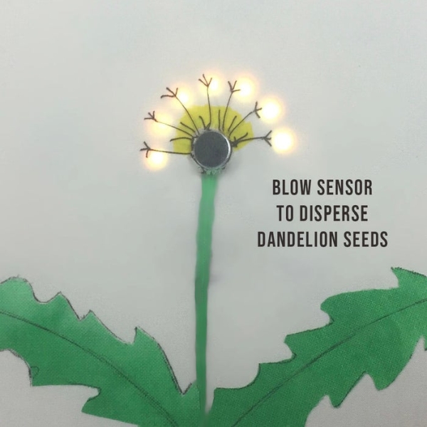
This project shows how to make an interactive picture of a dandelion. It starts as a yellow flower with LED’s for petals then changes into a white dandelion clock, which can be blown on to make the seeds disperse.
It is based on a beautiful artwork by Qi Jie, whose picture was inspired by a single flower design by Jessie Thompson and Zachory Berta. I made mine on fabric and framed it in a tapestry hoop to go on the wall of the Tech and Textiles makerspace in Devon, England, as an example of a beginners project that combines sewing with Arduino.
Video of light painting by Qi Jie
Video of single flower design by Jessie Thompson and Zachory Berta
The code for both existing projects is available and I thought it would be easy to make, but the instructions were minimal and it took several attempts before I found a method that worked. So here are the full instructions and time saving tips for a remix that combines elements of both designs and tweaks of my own.
Details of what didn’t work for me are at the end for anyone who’s interested in why I chose this way.
Code for light painting by Qi Jie
Code for small flower picture by Jessie Thompson and Zachory Berta
Materials
- Arduino UNO
- Adafruit Ring of 12 Neopixels
- 5V Strip of 11 RGB LEDs
- Sound Microphone Sensor
- Jumper Wires
- 5V Rechargeable Battery with USB A connection
- Printer Cable (USB A to B cable)
- Glue Dots or Hot Glue
- A4 Card
- 30cm x 30cm Cream Cotton Fabric, such as an old pillowcase
- Green Fabric Paint
- Brown Cotton Thread
- 70cm x 50cm Corrugated Cardboard, such as pizza boxes
- Masking Tape
- 9 inch Embroidery Hoop to frame the picture
- 9 Self-Adhesive Velcro Tabs
Tools
- A computer with Arduino IDE downloaded
- Soldering Iron and Lead-Free Solder
- Breadboard for testing circuit
- Wire Stripper/Cutters
- Sewing Needle
- Pen
- Scissors
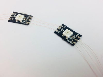
Step 1: Prepare the NeoPixel Ring
Solder different color wires to each of the power, ground and data pads on the back of the NeoPixel ring.
If you have a different version of the ring, your wires may not be in the same position as the photo of mine.
Make a note of which wires are for input and output as well as positive, data and ground because the markings for these are on the underside of the ring and won’t be visible when the ring is in position.
Step 2: Cut the Strips of LEDs
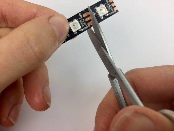
Cut 11 individual LEDs from a strip of RGB LEDs, taking care to cut along the centre line to leave solder pads on both sides of the cut. Dab a blob of solder on the top side of each pad.
Step 3: Solder the LEDs
Make a hole in the middle of the card to fit the microphone. Using glue dots, stick the ring of neo pixels and individual LEDs in position as shown, making sure all the arrows on the LEDs will line up the same way when daisy chained together.
Solder the output wires from the ring to the first individual LED, matching the positive, ground and data wires to the same pads on both LEDs.
The quickest and easiest way I found to join the LEDs together is to strip a jumper wire into separate copper strands. Attach one strand to link each of the soldered pads on the LEDs to the next one, matching positive, data and ground. It just takes a quick touch of a hot soldering iron because the pads have been pre-soldered in the previous step. Instead of cutting the wires at this stage, take them across the top of the LED to reach the soldered pads on the other side. Making sure no wires cross or touch each other, solder to those pads and continue round to the input side of the last LED.
Don’t attach a wire to the output side of the last LED. Unlike some LEDs you may be familiar with, you don’t need to complete a round circuit that takes power back to ground as you’ve been wiring separate ground and positive lines all the way along. Cut all the wires that go across the top of the LEDs so that you only have wires linking between them.
Tip: To prevent wires touching when going round corners, thread each one back into a small strip of plastic insulation that was previously removed.
Step 4: Preparing the Back
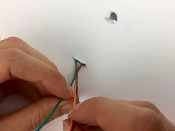
Make another hole in the white card for the input wires and push them through.
Separate the two rings of the tapestry hoop. Draw round the outside of the smallest ring on 5 pieces of corrugated card and cut out. Cut holes in the middle of 3 of the circles approximately 2cm in from the edge to make rings and cut a 5mm slit in each one. Glue the rings on top of each other, lining up the slits, and stick this to one of the remaining circles of card.
Step 5: Wiring the Microphone and Arduino
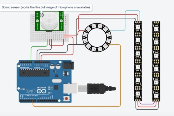
Wire your Arduino to the microphone sensor and the LED ring as shown. I used TinkerCad to create the circuit diagram, which doesn’t have a microphone picture so I’ve substituted another sensor that uses the same pins and works the same way in the simulation.
To view the simulation, go to https://www.tinkercad.com/things/5cgI2wluA0c. Drag the circle attached to the sensor onto the active area to simulate blowing into the microphone. The LEDs are in strips on 6, so the last LED in the simulation isn’t part of the design and doesn’t light up.
Step 6: Programming the Arduino
Open Arduino IDE on your computer and start a new Sketch
Delete everything inside the sketch and copy and paste this code into it instead
// Adapted using NeoPixel Ring simple sketch (c) 2013 Shae Erisson<br>//and sensor code from <a href="https://www.hackster.io/ingo-lohs/first-test-37-sensor-kit-v2-0-from-elegoo-7-37-ba2d7d" rel="nofollow"> https://www.hackster.io/ingo-lohs/first-test-37-s...</a>

#include <Adafruit_NeoPixel.h>

// Which pin on the Arduino is connected to the NeoPixels?
#define PIN            6

// How many NeoPixels are attached to the Arduino?
#define NUMPIXELS      23

// When we setup the NeoPixel library, we tell it how many pixels, and which pin to use to send signals.
// Note that for older NeoPixel strips you might need to change the third parameter--see the strandtest
// example for more information on possible values.
Adafruit_NeoPixel pixels = Adafruit_NeoPixel(NUMPIXELS, PIN, NEO_GRB + NEO_KHZ800);

int delayval = 500; // delay for half second
int sensorPin  =  A0;     // select the input pin for the sensor
int sensorValue =  0;     // variable to  store  the value  coming  from  the sensor

const int threshold = 200;   // an arbitrary threshold level that's in the range of the analog input

void setup() {

 pixels.begin(); // This initializes the NeoPixel library.
  pixels.setBrightness(20); // Set brightness
  Serial.begin(9600);
}

void loop() {

  // For a set of NeoPixels the first NeoPixel is 0, second is 1, all the way up to the count of pixels minus one.

  // Dandelion LEDs

  // pixels.Color takes RGB values, from 0,0,0 up to 255,255,255
  pixels.setPixelColor(0, pixels.Color(0, 0, 0)); // Off.
  pixels.setPixelColor(1, pixels.Color(0, 0, 0)); // Off.
  pixels.setPixelColor(2, pixels.Color(0, 0, 0)); // Off.
  pixels.setPixelColor(3, pixels.Color(0, 0, 0)); // Off.
  pixels.setPixelColor(4, pixels.Color(0, 0, 0)); // Off.
  pixels.setPixelColor(5, pixels.Color(255, 165, 0)); // Orange.
  pixels.setPixelColor(6, pixels.Color(255, 165, 0)); // Orange.
  pixels.setPixelColor(7, pixels.Color(255, 165, 0)); // Orange.
  pixels.setPixelColor(8, pixels.Color(255, 165, 0)); // Orange.
  pixels.setPixelColor(9, pixels.Color(255, 165, 0)); // Orange.
  pixels.setPixelColor(10, pixels.Color(255, 165, 0)); // Orange.
  pixels.setPixelColor(11, pixels.Color(255, 165, 0)); // Orange.
  pixels.setPixelColor(12, pixels.Color(0, 0, 0)); // Off.
  pixels.setPixelColor(13, pixels.Color(0, 0, 0)); // Off.
  pixels.setPixelColor(14, pixels.Color(0, 0, 0)); // Off.
  pixels.setPixelColor(16, pixels.Color(0, 0, 0)); // Off.
  pixels.setPixelColor(17, pixels.Color(0, 0, 0)); // Off.
  pixels.setPixelColor(18, pixels.Color(0, 0, 0)); // Off.
  pixels.setPixelColor(19, pixels.Color(0, 0, 0)); // Off.
  pixels.setPixelColor(20, pixels.Color(0, 0, 0)); // Off.
  pixels.setPixelColor(21, pixels.Color(0, 0, 0)); // Off.
  pixels.setPixelColor(22, pixels.Color(0, 0, 0)); // Off.

  pixels.show(); // This sends the updated pixel color to the hardware.

  delay(delayval*6);//Gradual change from flower to seed head

    // pixels.Color takes RGB values, from 0,0,0 up to 255,255,255
  pixels.setPixelColor(0, pixels.Color(0, 0, 0)); // Off.
  pixels.setPixelColor(1, pixels.Color(0, 0, 0)); // Off.
  pixels.setPixelColor(2, pixels.Color(0, 0, 0)); // Off.
  pixels.setPixelColor(3, pixels.Color(0, 0, 0)); // Off.
  pixels.setPixelColor(4, pixels.Color(0, 0, 0)); // Off.
  pixels.setPixelColor(5, pixels.Color(226,246,255)); // bluishwhite
  pixels.setPixelColor(6, pixels.Color(255, 165, 0)); // Orange.
  pixels.setPixelColor(7, pixels.Color(226,246,255)); // bluishwhite
  pixels.setPixelColor(8, pixels.Color(255, 165, 0)); // Orange.
  pixels.setPixelColor(9, pixels.Color(226,246,255)); // bluishwhite
  pixels.setPixelColor(10, pixels.Color(255, 165, 0)); // Orange.
  pixels.setPixelColor(11, pixels.Color(226,246,255)); // bluishwhite.
  pixels.setPixelColor(12, pixels.Color(0, 0, 0)); // Off.
  pixels.setPixelColor(13, pixels.Color(0, 0, 0)); // Off.
  pixels.setPixelColor(14, pixels.Color(0, 0, 0)); // Off.
  pixels.setPixelColor(16, pixels.Color(0, 0, 0)); // Off.
  pixels.setPixelColor(17, pixels.Color(0, 0, 0)); // Off.
  pixels.setPixelColor(18, pixels.Color(0, 0, 0)); // Off.
  pixels.setPixelColor(19, pixels.Color(0, 0, 0)); // Off.
  pixels.setPixelColor(20, pixels.Color(0, 0, 0)); // Off.
  pixels.setPixelColor(21, pixels.Color(0, 0, 0)); // Off.
  pixels.setPixelColor(22, pixels.Color(0, 0, 0)); // Off.

  pixels.show(); // This sends the updated pixel color to the hardware.

    delay(delayval*6);

  //  Seed head LEDs

 pixels.setPixelColor(0, pixels.Color(226, 246, 255)); // Bluish white.
  pixels.setPixelColor(1, pixels.Color(0,0,0)); //off
  pixels.setPixelColor(2, pixels.Color(226, 246, 255)); // Bluish white.
  pixels.setPixelColor(3, pixels.Color(0,0,0)); //off
  pixels.setPixelColor(4, pixels.Color(226, 246, 255)); // Bluish white.
  pixels.setPixelColor(5, pixels.Color(255, 165, 0)); // Orange.
  pixels.setPixelColor(6, pixels.Color(226, 246, 255)); // Bluish white.
  pixels.setPixelColor(7, pixels.Color(255, 165, 0)); // Orange.
  pixels.setPixelColor(8, pixels.Color(226, 246, 255)); // Bluish white.
  pixels.setPixelColor(9, pixels.Color(255, 165, 0)); // Orange.
  pixels.setPixelColor(10, pixels.Color(226, 246, 255)); // Bluish white.
  pixels.setPixelColor(11, pixels.Color(226, 246, 255)); //off
  pixels.setPixelColor(12, pixels.Color(0, 0, 0)); // Off.
  pixels.setPixelColor(13, pixels.Color(0, 0, 0)); // Off.
  pixels.setPixelColor(14, pixels.Color(0, 0, 0)); // Off.
  pixels.setPixelColor(16, pixels.Color(0, 0, 0)); // Off.
  pixels.setPixelColor(17, pixels.Color(0, 0, 0)); // Off.
  pixels.setPixelColor(18, pixels.Color(0, 0, 0)); // Off.
  pixels.setPixelColor(19, pixels.Color(0, 0, 0)); // Off.
  pixels.setPixelColor(20, pixels.Color(0, 0, 0)); // Off.
  pixels.setPixelColor(21, pixels.Color(0, 0, 0)); // Off.
  pixels.setPixelColor(22, pixels.Color(0, 0, 0)); // Off.

  pixels.show(); // This sends the updated pixel color to the hardware.

  delay(delayval*3); // Delay for a period of time (in milliseconds).

  pixels.setPixelColor(0, pixels.Color(226, 246, 255)); // Bluish white.
  pixels.setPixelColor(1, pixels.Color(0,0,0)); //off
  pixels.setPixelColor(2, pixels.Color(226, 246, 255)); // Bluish white.
  pixels.setPixelColor(3, pixels.Color(226, 246, 255)); // Bluish white.
  pixels.setPixelColor(4, pixels.Color(226, 246, 255)); // Bluish white.
  pixels.setPixelColor(5, pixels.Color(255, 165, 0)); // Orange.
  pixels.setPixelColor(6, pixels.Color(226, 246, 255)); // Bluish white.
  pixels.setPixelColor(7, pixels.Color(255, 165, 0)); // Orange.
  pixels.setPixelColor(8, pixels.Color(226, 246, 255)); // Bluish white.
  pixels.setPixelColor(9, pixels.Color(226, 246, 255)); // Bluish white.
  pixels.setPixelColor(10, pixels.Color(226, 246, 255)); // Bluish white.
  pixels.setPixelColor(11, pixels.Color(226,246,255)); //Bluish white.
  pixels.setPixelColor(12, pixels.Color(0, 0, 0)); // Off.
  pixels.setPixelColor(13, pixels.Color(0, 0, 0)); // Off.
  pixels.setPixelColor(14, pixels.Color(0, 0, 0)); // Off.
  pixels.setPixelColor(16, pixels.Color(0, 0, 0)); // Off.
  pixels.setPixelColor(17, pixels.Color(0, 0, 0)); // Off.
  pixels.setPixelColor(18, pixels.Color(0, 0, 0)); // Off.
  pixels.setPixelColor(19, pixels.Color(0, 0, 0)); // Off.
  pixels.setPixelColor(20, pixels.Color(0, 0, 0)); // Off.
  pixels.setPixelColor(21, pixels.Color(0, 0, 0)); // Off.
  pixels.setPixelColor(22, pixels.Color(0, 0, 0)); // Off.

  pixels.show(); // This sends the updated pixel color to the hardware.

  delay(delayval*3); // Delay for a period of time (in milliseconds).

  pixels.setPixelColor(0, pixels.Color(226, 246, 255)); // Bluish white.
  pixels.setPixelColor(1, pixels.Color(226, 246, 255)); // Bluish white.
  pixels.setPixelColor(2, pixels.Color(226, 246, 255)); // Bluish white.
  pixels.setPixelColor(3, pixels.Color(226, 246, 255)); // Bluish white.
  pixels.setPixelColor(4, pixels.Color(226, 246, 255)); // Bluish white.
  pixels.setPixelColor(5, pixels.Color(226, 246, 255)); // Bluish white.
  pixels.setPixelColor(6, pixels.Color(226, 246, 255)); // Bluish white.
  pixels.setPixelColor(7, pixels.Color(226, 246, 255)); // Bluish white.
  pixels.setPixelColor(8, pixels.Color(226, 246, 255)); // Bluish white.
  pixels.setPixelColor(9, pixels.Color(226, 246, 255)); // Bluish white.
  pixels.setPixelColor(10, pixels.Color(226, 246, 255)); // Bluish white.
  pixels.setPixelColor(11, pixels.Color(226, 246, 255)); // Bluish white.
  pixels.setPixelColor(12, pixels.Color(0, 0, 0)); // Off.
  pixels.setPixelColor(13, pixels.Color(0, 0, 0)); // Off.
  pixels.setPixelColor(14, pixels.Color(0, 0, 0)); // Off.
  pixels.setPixelColor(16, pixels.Color(0, 0, 0)); // Off.
  pixels.setPixelColor(17, pixels.Color(0, 0, 0)); // Off.
  pixels.setPixelColor(18, pixels.Color(0, 0, 0)); // Off.
  pixels.setPixelColor(19, pixels.Color(0, 0, 0)); // Off.
  pixels.setPixelColor(20, pixels.Color(0, 0, 0)); // Off.
  pixels.setPixelColor(21, pixels.Color(0, 0, 0)); // Off.
  pixels.setPixelColor(22, pixels.Color(0, 0, 0)); // Off.

  pixels.show(); // This sends the updated pixel color to the hardware.

  delay(delayval); // Delay for a period of time (in milliseconds).

  // Read the sensor value and display it in the serial monitor
  sensorValue = analogRead(sensorPin);
  Serial.println(sensorValue);
  delay(250);

  // While sensor value is less than threshold, check the sensor value and print it in the serial monitor. When the value is above threshold, the sketch can continue
  while (sensorValue < threshold) {
  sensorValue = analogRead(sensorPin);
  Serial.println(sensorValue);
  delay(250);
  }

  // First wind LEDs

  pixels.setPixelColor(0, pixels.Color(0, 0, 0)); // Off.
  pixels.setPixelColor(1, pixels.Color(0, 0, 0)); // Off.
  pixels.setPixelColor(2, pixels.Color(0, 0, 0)); // Off.
  pixels.setPixelColor(3, pixels.Color(0, 0, 0)); // Off.
  pixels.setPixelColor(4, pixels.Color(0, 0, 0)); // Off.
  pixels.setPixelColor(5, pixels.Color(0, 0, 0)); // Off.
  pixels.setPixelColor(6, pixels.Color(0, 0, 0)); // Off.
  pixels.setPixelColor(7, pixels.Color(0, 0, 0)); // Off.
  pixels.setPixelColor(8, pixels.Color(0, 0, 0)); // Off.
  pixels.setPixelColor(9, pixels.Color(0, 0, 0)); // Off.
  pixels.setPixelColor(10, pixels.Color(0, 0, 0)); // Off.
  pixels.setPixelColor(11, pixels.Color(0, 0, 0)); // Off.
  pixels.setPixelColor(12, pixels.Color(226, 246, 255)); // Bluish white.
  pixels.setPixelColor(13, pixels.Color(226, 246, 255)); // Bluish white.
  pixels.setPixelColor(14, pixels.Color(226, 246, 255)); // Bluish white.
  pixels.setPixelColor(15, pixels.Color(226, 246, 255)); // Bluish white.
  pixels.setPixelColor(16, pixels.Color(226, 246, 255)); // Bluish white.
  pixels.setPixelColor(17, pixels.Color(0, 0, 0)); // Off.
  pixels.setPixelColor(18, pixels.Color(0, 0, 0)); // Off.
  pixels.setPixelColor(19, pixels.Color(0, 0, 0)); // Off.
  pixels.setPixelColor(20, pixels.Color(0, 0, 0)); // Off.
  pixels.setPixelColor(21, pixels.Color(0, 0, 0)); // Off.
  pixels.setPixelColor(22, pixels.Color(0, 0, 0)); // Off.

  pixels.show(); // This sends the updated pixel color to the hardware.

  delay(delayval); // Delay for a period of time (in milliseconds).

  // Second wind LEDs

  pixels.setPixelColor(0, pixels.Color(0, 0, 0)); // Off.
  pixels.setPixelColor(1, pixels.Color(0, 0, 0)); // Off.
  pixels.setPixelColor(2, pixels.Color(0, 0, 0)); // Off.
  pixels.setPixelColor(3, pixels.Color(0, 0, 0)); // Off.
  pixels.setPixelColor(4, pixels.Color(0, 0, 0)); // Off.
  pixels.setPixelColor(5, pixels.Color(0, 0, 0)); // Off.
  pixels.setPixelColor(6, pixels.Color(0, 0, 0)); // Off.
  pixels.setPixelColor(7, pixels.Color(0, 0, 0)); // Off.
  pixels.setPixelColor(8, pixels.Color(0, 0, 0)); // Off.
  pixels.setPixelColor(9, pixels.Color(0, 0, 0)); // Off.
  pixels.setPixelColor(10, pixels.Color(0, 0, 0)); // Off.
  pixels.setPixelColor(11, pixels.Color(0, 0, 0)); // Off.
  pixels.setPixelColor(12, pixels.Color(0, 0, 0)); // Off.
  pixels.setPixelColor(13, pixels.Color(0, 0, 0)); // Off.
  pixels.setPixelColor(14, pixels.Color(0, 0, 0)); // Off.
  pixels.setPixelColor(15, pixels.Color(0, 0, 0)); // Off.
  pixels.setPixelColor(16, pixels.Color(0, 0, 0)); // Off.
  pixels.setPixelColor(17, pixels.Color(226, 246, 255)); // Bluish white.
  pixels.setPixelColor(18, pixels.Color(226, 246, 255)); // Bluish white.
  pixels.setPixelColor(19, pixels.Color(226, 246, 255)); // Bluish white.
  pixels.setPixelColor(20, pixels.Color(226, 246, 255)); // Bluish white.
  pixels.setPixelColor(21, pixels.Color(226, 246, 255)); // Bluish white.
  pixels.setPixelColor(22, pixels.Color(226, 246, 255)); // Bluish white.

  pixels.show(); // This sends the updated pixel color to the hardware.

  delay(2000); // Delay for a period of time (in milliseconds).

}
Attach your Arduino to the computer with the USB printer cable
Go to Tools > Board and select the Arduino/Genuino UNO board
Go to Port and make sure you’ve got the board connected to the right USB port. If you’re unsure you can unplug the Arduino and see which port disappears from the list. Plug it back in and the port will be listed again.
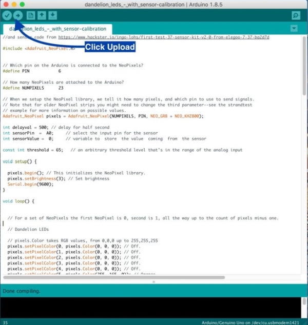
Upload the sketch by clicking on the Upload icon, shown in the annotated photo. Lights should flash on the Arduino while it uploads. When it finishes uploading half the LEDs on the neo pixel ring will light up yellow and then change to a full ring of white lights. Blow on the microphone to test the circuit. The LEDs in the outer layers should light up in turn. Check the solder on any LEDs that don’t work.
Step 7: Changing the Colours, Brightness and Sensor Threshold
Colors
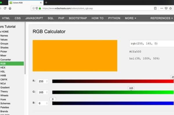
The colours of the LEDs are set using RGB (Red Green Blue) colour values. If you prefer to use different colors than I’ve used you can find the values for the colours you want by using an online RGB colour calculator such as www.w3schools.com/colors/colors_rgb.asp
To turn an LED off, use the values 0, 0, 0.
To set the LED to white, use the values 255, 255, 255. The code in the previous step uses a bluish white with the values 226, 246, 255 and an orange with the values of 255, 165, 0.
Brightness
To change the brightness of the LEDs, go to the void setup section of the code and find the following line of code:
pixels.setBrightness(20); // Set brightness
Edit the number in the brackets to change the brightness of the LEDs.
Sensor Threshold
When you run the program, half the NeoPixel ring starts off yellow to represent a flower and gradually changes to a full circle of white LEDs to represent the seed head. At this point the program should pause until you blow on the microphone sensor. If the program continues and lights up the outer layers of LEDs without activation from the sensor, go to the void setup section of the code and lower the value shown below. Increase the value if the program pauses but doesn’t respond when you blow on the sensor.
const int threshold = 200;
Step 8: Making the Circuit More Permanent
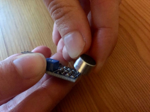
When the circuit works, unplug the Arduino from the computer and remove the microphone sensor from the breadboard. Solder wires from the Arduino to the microphone sensor to make the same circuit more permanent. Push the microphone through the hole in the card from behind. If necessary, carefully bend the microphone by 90 degrees so the board can lie flat behind the card. Attach the battery to the Arduino using the printer cable and the whole sequence should work.
Step 9: Create a Picture
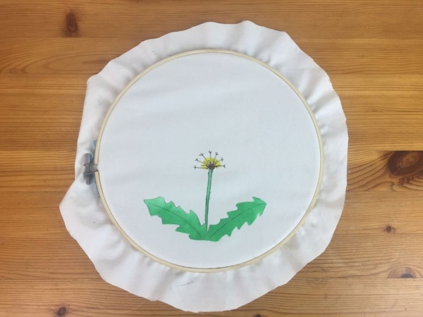
Make a hole in your fabric where you want the microphone. I used a hot soldering iron to burn a small hole and trimmed it with scissors until the microphone fitted through. Paint and stitch your flower on the fabric. When the paint dries, attach the painting to the embroidery hoop and trim away excess fabric, leaving a small border.
To see if any of the circuit components show through the fabric, temporarily place the fabric and hoop on top of the card with the microphone showing through the hole. If necessary, cover the circuit with layers of masking tape, checking occasionally, until the components don’t show anymore. The LEDs are bright enough to be seen through a layer of masking tape. If you have to add even more layers you can make the LEDs brighter by adjusting your code as shown in Step 7.
Place the fabric and hoop back on top of the card as before and secure in place by gluing the extra fabric over the back of the card.
Step 10: Putting It Together
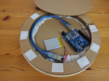
Glue the white card onto the corrugated cardboard circle, enclosing the microphone, but not the Arduino and battery pack, which need to go round the edge of the cardboard with the wires passing through the slits.
Attach the last circle of cardboard with Velcro so that you can access the battery. Make a hole in the cardboard where you want to hang it on a hook on the wall.
Step 11: Learning From Mistakes
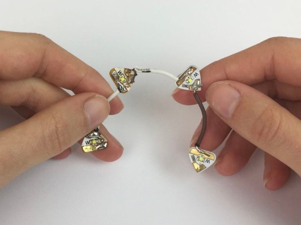
My first attempt was with circuit stickers and copper tape. Circuit stickers are tiny LEDs surface mounted onto stickers with copper pads. They come from Qi Jie’s company, Chibitroniks, and I thought they’d be perfect.
I couldn’t get a reliable connection using copper tape or silver tape and when I soldered wire to the stickers I could still only get a series of 3 LED stickers to light using a 9V battery. It became clear they are not intended for multi light projects as I’d hoped. When I looked more closely at a web page about circuit stickers, a project with 4 lights turned out to be a different type of LEDs. I could power circuit stickers with a 12V battery but it would be too bulky to fit inside the picture.
Then I tried sewable LEDs. I thought having only power and ground would be easier to wire than programmable LEDs which have power, ground and data lines. But it turned out to be a more complicated circuit needing an extra power supply and a MOSFET, which I didn’t have. I could have used sewable NeoPixels, but they are more expensive.
So after a few false starts, I ended up with a string of programmable LEDs which are cheap and easy to use.
Read more: Interactive Dandelion
- How do I connect the NeoPixel ring to the individual LEDs?
Solder the output wires from the ring to the first individual LED, matching positive, ground, and data wires, then link subsequent LEDs using stripped copper strands. - Can I change the colors of the LEDs in the code?
Yes, you can modify the RGB values in the code; for example, use 255, 255, 255 for white or 0, 0, 0 to turn an LED off. - What is the best way to prevent wires from touching when routing them around corners?
Thread each wire back into a small strip of plastic insulation previously removed to keep them separated. - Does the microphone sensor need to be connected to a specific pin?
The code specifies using analog pin A0 for the sensor input. - How do I adjust the sensitivity of the blowing sensor?
You can change the threshold value in the void setup section; lower the number if it triggers too easily or increase it if it does not respond to blowing. - Can I power this project without a computer after assembly?
Yes, by soldering the circuit permanently and connecting the 5V rechargeable battery to the Arduino using a printer cable. - Why did the author choose programmable LEDs over circuit stickers?
Circuit stickers were difficult to connect reliably and required a bulky 12V battery, whereas programmable LEDs are cheap and easy to use. - How many total pixels are defined in the sketch?
The code defines NUMPIXELS as 23, combining the 12-pixel ring and 11 individual LEDs.