Summary of An Intel Galileo Walkthrough using arduino
The Intel Galileo is a new embedded board combining x86 technology with Arduino compatibility. Based on the Intel Quark X1000 SoC, it runs GNU/Linux while supporting Arduino IDE sketches as user-space processes. It features hardware and software compatibility with the Arduino Uno R3, allowing the use of standard shields. The board includes PC-like interfaces such as Ethernet, USB Host/Client ports, mini-PCI Express, and Micro-SD slots, offering significant processing power over traditional microcontrollers.
Parts used in the Intel Galileo Project:
- Intel Quark X1000 SoC
- Intel Pentium 400MHz 32-bit processor
- 16 KBytes L1 cache
- 512 KByte embedded SRAM
- Real Time Clock (RTC)
- 3V button battery
- Ethernet 10/100 Mb connector
- PCI Express mini-card slot
- WiFi card (optional)
- USB Host 2.0 connector
- USB Client connector
- JTAG 10-pin debugging connector
- Reboot button
- Arduino sketch reset button
- 8 MB Legacy SPI Flash memory
- 512-Kbyte SRAM
- 256 MB DRAM
- 11-Kbyte EEPROM memory
- Micro SDCard slot
- 3.5mm jack connector
- AD7298 integrated circuit
- ICSP 6-pin connector
Despite the Arduino YUN was presented just recently, already a new board that is compatible with GNU/Linux has been released. This one is based on x86 technology and made by Intel, the leader of this technology.
Evolution of embedded technologies could be considered a fact if a giant like Intel decided to participate with his “interpretation” of the phenomenon. Embedded technology combines the power and flexibility of an operating system such as GNU/Linux and the ability to manage peripheral I/Os according to the typical specifications of the microcontroller, all made with architectures equipped with one or more processors.
“Galileo” is based on the Intel Quark X1000 SoC, a system built around a 32 bit Pentium class processor, single-core, single-thread, compatible with ISA architecture (Instruction Set Architecture), which works at speeds up to 400 MHz. Galileo is the first Intel board designed to be hardware and software compatible with the specifications of Arduino Uno R3. De facto a small PC that you can assemble with shields designed for Arduino. The pinout is compatible with Arduino Uno, and the I/O terminals can work at either 5-V to 3.3 by placing a jumper, which activates the level converters for each pin. The native voltage is 3.3V, the 5V is obtained with the conversion. While “Galileo” is software compatible with Arduino’s IDE, the operating system is a GNU/Linux distribution, which “runs” on the board only processor. The Arduino sketches are run as processes in the user space of the GNU/Linux operating system. The available IDE compiles the sketches in “.elf” format, an executable binary format, originally developed by UNIX System Laboratories and commonly used in GNU/Linux.
Intel Galileo Specification
Being developed from a family of PC processors, the “Galileo” board has a whole series of connectors, bus and doors, typical of PCs standard, which are added to the classic Arduino’s devices.
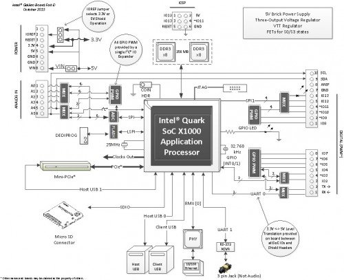
Look at the block diagram of the board: a mini-PCI Express connector, one 100 Mb Ethernet port, a slot for a Micro-SD, RS-232 serial port, a USB Host port and a USB Client port can be spotted. There is also a 8Mbyte flash NOR memory.
Galileo requires a 5V supply by the coaxial power connector. In this regard there is a recommendation clearly highlighted in the Intel instructions: it is important to give power to the board by the power connector before connecting it to a PC for programming by USB cable, otherwise you could damage the board itself.
These are the main features of Galileo’s architecture:
-
Intel Pentium 400MHz 32-bit in ISA architecture (instruction set architecture) with 16 KBytes of L1 chache, 512 KByte embedded SRAM;
-
Real Time Clock (RTC) integrated. To keep it permanently active simply connect a 3V button battery to the appropriate pin;
-
Connector Ethernet 10/100 Mb;
-
One slot PCI Express mini-card in the PCIe 2.0 standard that can accommodate mini-PCIe cards half-height, possibly with an adapter. The slot has been designed specifically to connect a WiFi card usable with the WiFi library;
-
USB Host connector 2.0 able to support up to 128 USB devices;
-
A USB client connector that can be used both for downloading the sketch on the board and connecting USB 2.0-compatible devices;
-
Standard JTAG connector with 10-pin for debugging;
-
Button to reboot the processor;
-
Button to reset the Arduino’s sketch only;
-
Mass Storages – A 8 MB Legacy SPI Flash memory where is stored the GNU / Linux bootloader and the last sketch loaded. For the sketch could be reserved from 256Kbyte to 512KByte memory. A 512-Kbyte SRAM and 256 MB DRAM memory managed directly by the operating system;
-
A 11-Kbyte EEPROM memory that can be programmed from the sketchs with the EEPROM library;
-
A slot for a micro SDCard up to 32GByte capacity;
-
The USB Connector can accommodate all types of mass storage devices compatible with USB 2.0 standard;
-
3.5mm jack connector allows you to use a second serial port standard UART. Notice that this is not an audio input / output.
Galileo Arduino-compatible connector
Let’s look in more detail the devices compatible with Arduino’s architecture;
-
14 pin reproducing Arduino’s I/O inputs, six of which can be used as PWM output (Pulse Width Modulation). Each of the 14 pin can be configured as input or output using the classic pinMode, digitalWrite, and digitalRead. Pins support both 5 and 3.3 V levels and a current of 10mA output and 25mA input. Pull-up resistor can be configured from 5.6K to 10k Ohm and turned off by default configuration;
-
Analog input pins, A0 to A5, are connected to a AD7298 integrated. Each pin provides 12-bit resolution (4096 values between 0 and 5V);
-
Pins A4 and A5, respectively SDA and SCL, support the communication protocol I2C (TWI) and can be interfaced with the Wire library;
-
The SPI bus is configured to 4MHz for compatibility with Arduino’s boards but may be increased to 25MHz. Galileo board can operate only as a master in SPI communication.
-
UART, the serial port is connected to pins 0 (RX) and 1 (TX);
-
ICSP 6-pin connector for in-circuit programming, is positioned on the board in order to be compatible with the existing shields;
-
VIN pin allows to give power to the board directly instead of using the coaxial power connector. You must provide a voltage stabilized to 5V, otherwise you could damage the board;
-
5V output pin provides a maximum current of 800mA;
-
3.3V output pin provides a maximum current of 800mA;
-
GND ground pin;
-
IOREF pin can be configured to 3.3V or 5V by a jumper selector;
-
RESET led to LOW level allows the reset of the sketch. It is used to bring the reset button on the shields that do not allow access to the button on the board;
-
AREF is the voltage reference for the ADC convertors. You cannot use this pin on the Galileo board.
For more detail: An Intel Galileo Walkthrough
- What operating system does the Intel Galileo run?
The board runs a GNU/Linux distribution on its single processor. - Can I use Arduino Uno shields with the Galileo?
Yes, the Galileo is hardware and software compatible with Arduino Uno R3 specifications. - How do I switch between 5V and 3.3V logic levels?
You must place a jumper to activate the level converters for each pin. - What is the recommended power sequence for programming?
You should supply power via the coaxial connector before connecting the USB cable to avoid damaging the board. - Does the Galileo support WiFi connectivity?
Yes, you can connect a WiFi card using the dedicated mini-PCI Express slot. - What is the native voltage of the Galileo board?
The native voltage is 3.3V, with 5V obtained through conversion. - How many analog input pins are available?
There are six analog input pins labeled A0 to A5. - Can the Galileo operate as an SPI slave device?
No, the board can only operate as a master in SPI communication.