
Summary of How to make and use the arduino as an Isp for an ATtiny85
This article provides a step-by-step guide to building a custom ATtiny programming shield for an Arduino. By assembling specific electronic components and connecting them according to the provided schematic, users can transform their Arduino into an In-System Programmer (ISP) for ATtiny microchips. The tutorial covers necessary materials, wiring connections between the ATtiny and Arduino pins, and software configuration within the Arduino IDE to enable programming of ATtiny 45 or 85 chips.
Parts used in the ATtiny Programming Shield:
- 3mm Red LED
- 3mm Green LED
- 10uf 50V electrolytic capacitor
- 8-pin 0.3" socket
- SPST tactile switch
- 220 ohm resistor
- Male pin headers
- 4-pin female sockets
- ATtiny 45 or 85 chip
- Soldering Iron
- Solder
- Tweezers
- Arduino UNO R2
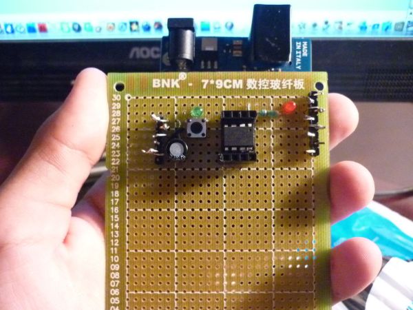
In this instructable I will show you how you can make your own Atting programming shield for the arduino and then use the arduino as a programmer.
Usually If you don’t have a shield you can do a breadboard version to program the ATtiny. (Step1)
But here I’ll show you how to program it and with a couple of components make a nice shield for the arduino, which makes programming much easier!
For more information on how to program the ATtiny click on: MIT High-Low Tech web page.
Hopefully you will be familiarized with the arduino environment, if not more info at Arduino.cc
And still, it’s quite easy to set everything up.
Step 1: Materials
Well, all the things you will need to make the shield are:
X1 3mm Red LED
X1 3mm Green LED
X1 10uf 50V electrolytic capacitor
X1 8-pin 0.3″ socket
X1 SPST tactile switch
X1 220 ohm resistor
X2 Male pin headers
X2 4-pin female sockets
X1 ATtiny 45 or 85
Things you might all ready have and will be needed:
Soldering Iron
Solder
Tweezers
And of course your Arduino, I made it on the Arduino UNO R2.
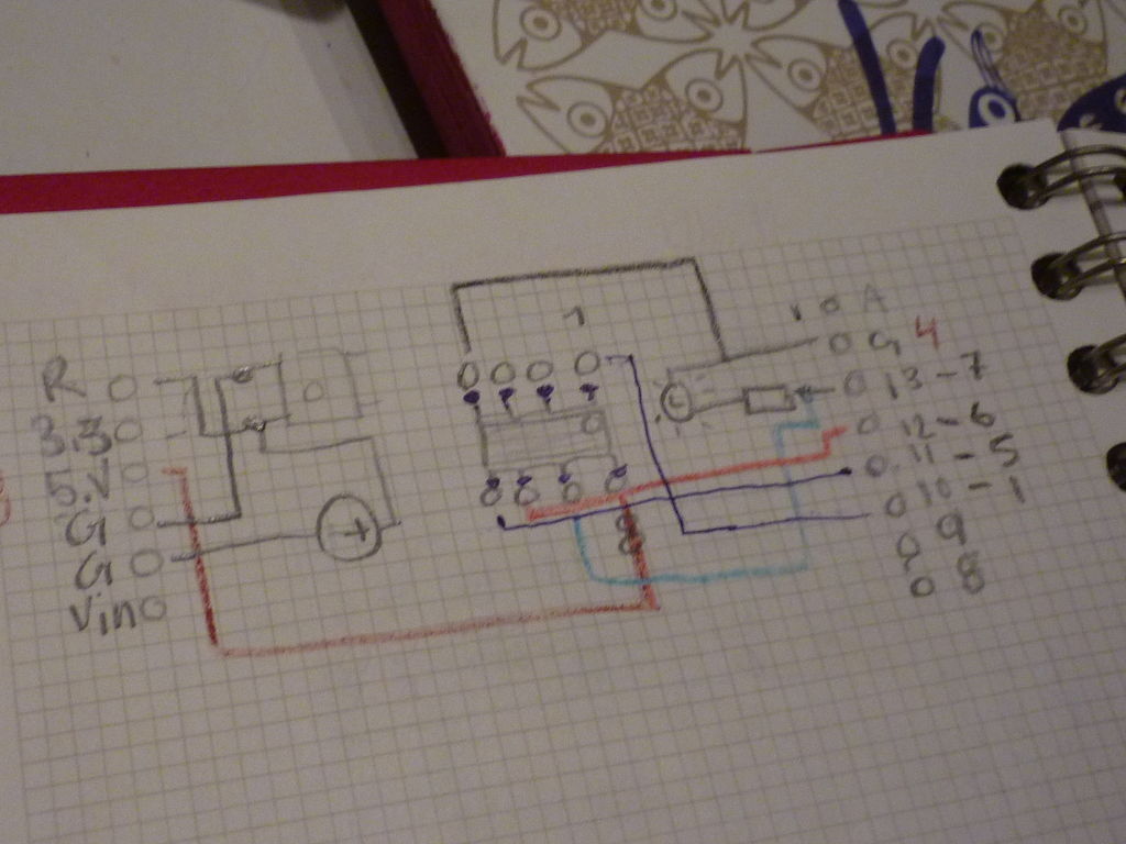
Step 2: Explaining the connections
Basically it’s like this:
Green LED goes to 3.3V on the arduino.
Red LED goes to the 220 ohm resistor which goes to pin 13.
Capacitor positive lead goes to one side of the pushbutton which goes to the reset pin.
Pin 1 on the ATtiny goes to pin 10 on arduino.
Pin 4 goes to ground.
Pin 5 goes pin 11.
Pin 6 goes to pin 12 .
Pin 7 goes to pin 13.
Pin 8 goes to 5v.
And well, all negatives go to the convenient ground pin.
I got the last two images from MIT Labs, hope it helps.
Step 3: The software
Start downloading the software from the MIT Webpage. The link is very clear!
Then, remember the folder called “arduino” That is in documents or in PC; My documents? Inside there there should be some sketches. Create a folder called “Hardware” and drag the ATtiny folder you downloaded before into “Hardware”.
Then open the arduino environment program. When open go to files/examples/arduinoISP. Upload that sketch and you are almost ready.
******************************************************************************************************************************************
Then when we finish the shield go to tools/board/ATtiny45/85 ( w/ arduino as ISP) (depending on your chip)
Attiny85
For more detail: How to make and use the arduino as an Isp for an ATtiny85
-
What is the primary purpose of this project?
To build a custom shield that allows an Arduino to function as a programmer for ATtiny microcontrollers. -
Which specific ATtiny chips are supported by this shield?
The shield is designed for the ATtiny 45 or ATtiny 85 chips. -
How do you connect the green LED in this circuit?
The green LED connects directly to the 3.3V pin on the Arduino. -
What is the connection path for the red LED?
The red LED connects to a 220 ohm resistor, which then connects to pin 13 on the Arduino. -
How should the capacitor be wired in the setup?
The positive lead of the capacitor goes to one side of the pushbutton, which connects to the reset pin. -
Where does pin 1 of the ATtiny connect on the Arduino?
Pin 1 of the ATtiny connects to pin 10 on the Arduino. -
Which software sketch must be uploaded to the Arduino to use it as a programmer?
You must upload the arduinoISP sketch found under files/examples/arduinoISP. -
Where should the downloaded ATtiny folder be placed within the Arduino environment?
The ATtiny folder should be dragged into a new "Hardware" folder located inside the main Arduino documents folder. -
How do you select the correct board settings after uploading the sketch?
Select ATtiny45/85 with Arduino as ISP from the tools/board menu depending on your specific chip.
