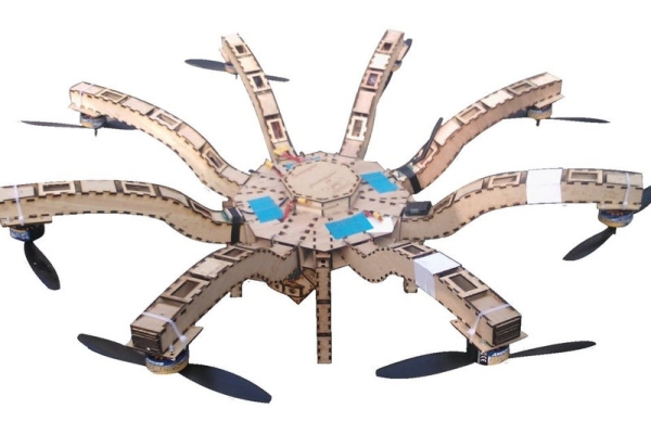
the photo you see was taken from my first ever copter which i built in 2 hours, what i had not mentioned was my first copter used a laser cut frame i designed and produced whilst in school.
This difference between this post and my other about building multirotors is this is mainly to do with designing a custom frame, however i thought rather than post links to the next tutorial, i would include it both for posterity and ease of use to those reading through and learning.
I currently pay to use my college laser cutter, unfortunately i have finished my course so i will not have the regular access i once had, part of the reason for submitting this instructable is in the hope i win the epilog challenge and can open a mini business selling my designs or at the very least open a world of possibility in design for me, not having to tiptoe around my college time table.
i hope you like my video intro
Step 1: New Designs
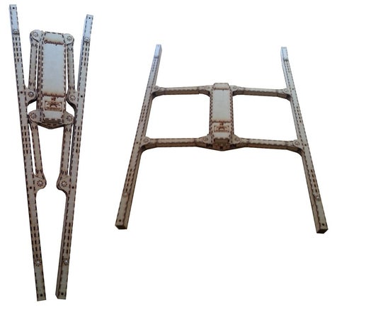
So as of 12th of july i made new frames for a new copter, but i decided i would push the limits of 2d designing a 3d model and camw up with some innovative designs,
I was in contact with a company that studies copter and found interesting design features that increased efficiency and stability.
Anging the motos on a 10 degree tilt increases stability significantly, Raising the motors above cg can make the copter more stable and mounting the motors under the frame rather than on top gave a 9% power and efficiency increase in flight due to no turbulence on the frame.
So i had that in mind for one frame, my other frame i wanted to be compact, so i could easily take it places without using up too much space.
So i wanted a folding frame but the conventional frame where the arms all fold down was a big issue, the joints had to be large to withstand the force they would be under and i would need 8 joins that add weight and unreliability,
So i came up with an entirely new frame that as far as i can see has never been made before. 🙂
Step 2: Designing the Laser Cut Frame
NEXT STEP, Photos of all the frames.
This step : design
When designing anything, you need a rough idea of how you want it to turn out, I usually have an idea in my mind but for some i recommend sketching and possibly taking measurements to figure out how you want the final model to look.
In this case, i took inspiration from the basic design of quadcopters, a simple x, but i felt that was too bland and so took parts from various frame designs and fashioned it into my frame.
I wanted something unique, that stood out not simply because of the material it was made from, but because of its design
In this case i wanted a dome to house the electronics and i wanted a unique looking set of arms that werent simply to hold the motors apart.
So i came up with this design.
(image 1)
I had made it to be relatively lightweight by removing large amounts of material (the helix design which is lots of squares cut out), but still needed it to be strong so i made a honeycomb design that was the many little squares cut out.
This halved the weight of the model, but it also hugely increase the cutting time, which i has to pay for , the longer the time to cut, the higher the price tag.
Which meant i had to compromise, so for larger parts i cut large pieces out.
so i had a few things that needed to be factored into the design to make it a viable frame.
Airflow (the props had some of their thrust lost when blowing onto the arms, so i had to make them thin or i ha to allow air flow)
Length (the props lose efficiency when close to other props, so i needed the arms to be long but not ridiculous)
weight (the copter loses flight time with weight, so i had to make it as light as possible)
Time Cost (because i pay for time used on the cutter, i had to make the design relatively simple)
Material strength (i could not design outside of the materials strengths, it could not be ultra thin as it could snap, or oscilate causing bad flight performance)
With the above factored in, The design can go ahead.
the trick is to design part by part, rather than design it all in one go, in this case, i designed the sides of the arms before i designed the top/bottom or plates, the arm was designed to be two x the length of the propellor i would use, this ensures the props would not be too close to each other or the board.
I tried to make the design as unified as possible which meant as few joints as possible thus as few weaknesses as possible.
so now i had to make it 3d, which meant in between the two side plates i had to put somthing that spaced them.
I could have printed out lots of side plates and stuck them together, but it would have used huge amounts of material and would have been heavy, instead i used spacer plates that slotter in with finger joints.
There were just slightly wider than the motor mounts and were 3mm thick, one thing to note when designing how they fit together is make sure you know the thickness of the material you are using.
In this case i used 3mm MDF so the finger joints were 10mm long and 3mm wide.
I tried to make the spacers as long as possible to make assembly easier and reduce cutting time .
I also had to make the plate the motor would mount onto.
I used dedicated spacers for this and used two samwidged together for extra strength.
at the time i did not know where the motor mount holes would be, so i cut generic equally spaced holes.
I now had to make the holes in the side plate that the spacers would fit into, so i made a line of boxes 100mm ling, 3mm tll and spaced 5mm apart like the fingers on the spacer plates, i then took the template and placed it on top of the side plate in the position needed..
It was very simple to do and the end result was a clean design.
i did make sure that the holes where the spacer plate slid into, would not compromise other parts of the frame making it weaker.
, i now had he arm designed, but i need to think how i would fit 4 of them together, so i h to make two plates that would clamp to the bottom and top of the arms, to hold them in place securely, this was ver simple, i measured the space i had available on the top arm and make a square that was double the size.
I then put two “fingers” that poked out of the arm that would slot into the top plate.
, i then had to put holes in the top plate that would allow those fingers to slot in, as you can see in the photo i did just that but i forgot the arm was actually in 3d and at the time only put in one set of holes for each arm.
So i had to correct this which was simple. i just copied the holes and spaced them the correct distance apart..
Now that i had a top plate, i decided i would simply cut out two and stick one to the bottom in the same manner.
I now had to design the holes for fitting the flight controller, this was difficult as again i did not have the measurements of controller at the time, so i made a generic design that would supports lots of mounting points.
I also put in lots of holes for any extra wiring that would need to be slotted through.
I now had to think about the dome, it would be too weak on its own, so i made a simple spacer that all the arms slotted into and make it far stronger.
the frame was now finished.
when i later cut it out and tried it, i found i had not completely thought out all the design, it was still a bit too heavy, the motor mount plate was a bit too weak and the dome needed strengthening.
So i took these ideas and proceeded to design many different frames, somewhere for fun and some were for practicality, you will see them all in the photos.
As you can see i have had a lot of fun designing the different frames, i have tried all sorts of designs, some for strength, some for practicality some for looks, some for nostalgia.
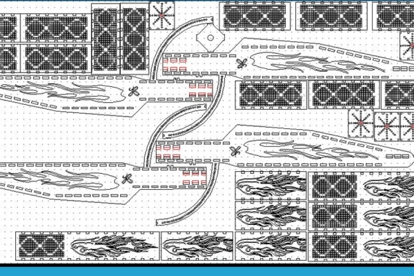
I have also included the image where i designed the frame and the image where i space it for the laser cutter bed.
Step 3: Building the Frame
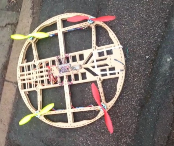
This is a very short step, I will explain about building the frame.
so when you design more complex frames, you may find assemble form lots of parts a ta confusing, this is why i like to lay the parts out in order of how they will be assembled, as 2d representation of the 3d final product effectively.
When it comes to attaching the parts together i would recommend wood glue or hot glue, because they are both not to messy, dry quickly and if needs be can be pulled apart to replace broken parts if necessary.
there is not much to assemble so i will simply show you photos of the final frames i made.
Step 4: Laser Cut Camera Gimbal
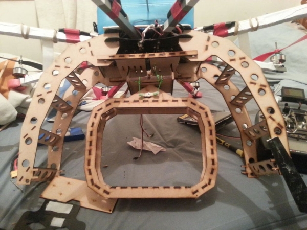
A few months on, i am looking to get into photography and aerial filming, but when searching for camera gimbals, i could only find very expensive gambles that can only hold a go pro and even more expensive gambles that can only just hold a dslr, this frustrated me , why should these laser cut gimbels be so expensive when they aren’t even very good.
SO i brought it upon myself to desin a strong nd practical gimble that is very inexpencive and that is exactly what i did!
This design take 45 minutes to cut and works out costing £2 in material and £20 in time cost
So here it is
I am very proud of the gimbal, it is very cleanly designed and very strong
Here is it working.
Step 5: The Multirotor
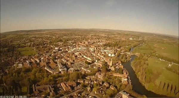
the photo you see was taken from my first ever copter which i built in 2 hours.
Price range can vary drastically, if you use this tutorial to build an quadcopter, your price range will be rouphly $290 without gps and telemetry however if you chose an octocopter you will be looking at upwards of $700
If you choose to buy a much cheaper flight controller board such as the kk2 from hobbyking.com you ill knock $70 off the price but sacrifice gps, telemetry battery voltage etc.
By Jared Reabow
Now before people plinky plonk on their keyboards “This is an Octocopter why is the title not Octocopter!!!!!” Understand you could build a Quadcopter – Hexacopter or quadcopter using this tutorial using identical parts , Even the Octocopter frame can be easily used for the 3 configurations by simply not fitting some arms 🙂
Also if you wish to use my instructable for profit making, just messege me and i will be more than happy to change the licence after chat 🙂
So lets get to it !!!!
I have made videos on doing everything but will also type out the relevant info.
But firstly the things you will need to build your own multirotor (note if it says 8x somthing, simply remove however many for the type of copter you are building, so a hex would be 6x)
Note that EVERYTHING you need can be bought from hobbyking.com simply search for the items described below
All required parts are listed below and are to be bought on hobbyking.com
2cm or smaller rubber bands
3mm wire
Hot glue gun and hot glue
Soldering Iron
Allen key set!!!!!
hobbking x930 frame
1 x 7a UBEC
8 x 30Amp esc’s any make or brand, just make sure they are 30Amp not 25 with 30burst.
30 bullet connector pairs 2.5mill or higher.
20pais of xt60 battery cnnectors
6 meters of silicone wire- 3 meters red – 3 meters black 26swg which is 3mm thick or more.
solder- preferred leaded.
8 x 12×4.7 props 4 clockwise 4 counter clockwise (order spares!)
8 x 850/750/700 kv outrunner motors bell type
lots of various sized shrink tubing.
sandpaper
(Radio)
Turnigy 9xr
Frysky Jr module with telemetry RX
2 x frsky voltmeters (note i am referring to small meters that are less than $5 each they have a red and black wire coming off each end with a servo plug on one end)
Male to male servo plugs x 18
Male to female extension leads (any length) x 10
stickyback velcro
4x 2200MAH 3s battery or any 2 battery combination that totals at least 8000MAH
(these should be bought from rctimer.com , they are available at hobbking but do not include some of the extras.
APM 2.5 flight controller board
MAvlink for telemetry (not required)
Ublox GPS
YOu may have to source this elsewhere ( buy some 2cm wide clothing elastic at least 2 meters
The videos will be posted in step 2, step 3 and later will be text based.
Read more: How to Make an Entire Drone/Multirotor and Camera Gimbal Using Laser Cut Parts
