Summary of How to Make a PIP-Boy using an Arduino
The article details the creation of a functional PIP-Boy 2000+ prototype inspired by the Fallout game series. The creator focuses on both hardware and software development, aiming for a practical, usable device rather than a mere replica. Key implemented features include GPS navigation, RFID-based inventory management, and a flashlight, while many features remain unimplemented. The project emphasizes progressive learning, perseverance, and skill-building in electronics, programming, and fabrication. The components chosen balance performance, cost, and accessibility, catering to intermediate electronics hobbyists.
Parts used in the PIP-Boy 2000+ Project:
- 4.3 inch 480x272 pixel LCD screen from 4D Systems (uLCD43)
- Arduino Duemilanove (Atmega 328)
- Adafruit Ultimate GPS module
- Sparkfun RFID-12 module with breakout board
- 8 position rotary switch (mil-spec metal body)
- 12mm² illuminated pushbutton switch (orange glow)
- Two rotary encoders (optional upgrade)
- Key lock power switch
- Various resistors: (11x) 10k ohm, 1x 220 ohm
- Machine screws and nuts: (4x) 6-32 3" screws, (4x) 6-32 nuts, (8x) 4-40 ½" screws, (8x) 4-40 nuts
- 9V battery clip
- 1/8" shaft diameter knob
- Mini prototyping board
- 1/8" thick polycarbonate sheet (2⅝" W x 4" L)
- Geiger counter module (optional upgrade)
- 1" Speaker (optional upgrade)
- Sculptor's mesh (metal wire sheet for casing, optional upgrade)
- RFID-button tag (optional upgrade)
- Soldering supplies and wires
- Hot glue gun and glue sticks
- Electrical tape (black)
- Various hand tools: screwdriver, rotary tool (e.g. Dremel), soldering iron, wire cutters/strippers, multimeter
- Heat shrink tubing
- Paint primer and military green spray paint (Krylon "Camo")
You may be wondering, what is a PIP-Boy exactly? If you don’t know, a PIP-Boy is a tool used by the main character in the well-liked Fallout video game series for navigating, detecting radiation, storing/playing data, and managing inventory. As a huge enthusiast of the franchise, I chose to create my own version, but not just a prop, I wanted a practical tool that I could actually utilize. This iteration serves as primarily a functional prototype and a foundation for future enhancements. My main aim is to construct a PIP-Boy 3000 completely from start, serving as my foundation to reach that level.
Hello, I’m also a huge enthusiast of Fallout! However, PIP-Boys appear nothing like that! Believe me, I understand. This prototype draws inspiration from both Pip Boy versions and computer terminals in the games.
However, hold on! If you are capable of producing this amount, why not proceed with constructing the 2000 or 3000A models as well? I won’t simply purchase a plaster replica of the FO3 PIP-Boy 3000 Clock and insert an iTouch inside. I aim for a device that works well, not one that only appears to work well. I truly desire to create a model from the game, but I cannot afford to make exact replicas until I have more money. Should I be the winner, creating the PIP-Boys will be much simpler. I have been strategizing my personal open source hardware business for some time, and acquiring a 3D printer or good camera would greatly assist me. Cast your vote for me and I guarantee you will not be let down.
Take a seat, open a cold Nuka-Cola, and enjoy the Instructable. At the conclusion, you should have gained knowledge and skills to create your own Personal Information Processor Boy.
For those interested in getting started on the build, skip ahead to the section labeled Hardware.
Step 1: History and Features
So how did I design all this?
How did I transition from looking at device pictures on a computer screen to physically holding a real device? Perseverance, a well-defined timetable, and abundant hot glue. I believe I have played around 200+ hours since November, without counting the numerous hours I spent playing Fallout 3 and New Vegas for “research” 😉 I divided the project into large sections and allocated specific daily tasks. I divided my tasks into two primary groups: software and hardware. After that, I divided everything into smaller sections, writing a function in one place, tweaking the speaker’s layout in another, and so forth. This prevented a lot of mental exhaustion and irritation that can arise from working on a complex project. My daily objectives were clear and achievable for me, and observing the gradual advancements gave me a confidence boost that enhanced the overall sense of manageability. However, I was far from perfect in my execution, quite the contrary. I often delayed things for several days. I came across software bugs that kept me baffled for hours. I repeatedly gazed at my monitor, perplexed by a hardware design issue, yet I persisted. A quote I love now is, “Don’t sacrifice your ultimate desires for immediate gratification,” it’s relevant to various life situations. It may be brief and concise, but it resonates deeply with me. My biggest desire is to enhance my skills as both an artist and engineer, to develop even more spectacular designs, and to eventually own my very own PIP-Boy, even though I often feel tempted to browse Reddit, watch Netflix, or sleep in. I could have invested a lot of money in research and design over the past half year.
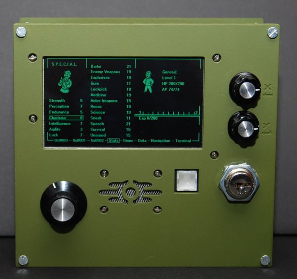
Okay, enough motivational mumbo jumbo, so what can the prototype PIP-Boy 2000+ do? Although many of the functions of the devices are purely for game mechanic reasons, there are still quite a few functions useful to those of us in the real world. Here’s a list of in-game features (based off of FO3 and FNV) and their status in development:
Automapping and waypoint navigation: (Partially Complete) Waypoints and simple GPS navigation is relatively easy, automaps without advanced laser rangefinders/sonar is not possible . Currently only latitude, longitude, heading, speed, altitude, and number of satellites used are displayed.
Moral status and local reputation: (Not Implemented) These can’t be automatically gauged, but the graphics would be trivial to add.
External interface to computers: (Partially Complete) The device must be disassembled in order to be reprogrammed, and no local data downloading is available for the time being. It would be neat to stick a decently sized flash drive in there, and even better if that information or the file system could be read on-screen.
Real-time health monitoring and feedback: (Not Implemented) there’s certainly no way to measure the health status of specific body parts or automatic notification of addiction, but I suppose the next best thing might be to add a heart rate monitor, although this would require the external chest strap. An accelerometer/pedometer to gauge steps taken and as a simple fitness measurement wouldn’t be too hard to add too.
Inventory status and item condition: (Partially Complete) I see no way for this to be automatic, but this version has RFID-reading capabilities, so some form of inventory management would be possible with unique tags for items, however crude.
Character level and experience: (Partially Complete) As the only real world task the PIP-Boy can be aware of is discovering a new location, that is the only way to “gain experience.” Although purely for fun and no practical reason, I could set this to gain experience/levels by traveling and have the user get to distribute skill points. Of course, you could always cheat since you have access to the code and could have whatever stats you wish, but that’s no fun 😉 Perks are not implemented.
Ambient radiation measurement and level of irradiation: (Partially Complete) There is a small working Geiger-counter module, but this is also for fun and should by no means be used for situations in which serious radiation detection is necessary. Measuring how much of a dosage you have absorbed in RADs is also impractical.
Flashlight:(Complete) Just like in the game, the prototype has an “overbright” mode, although the LCD is not terribly bright, it does glow decently. For another version, I’m considering just popping in some high-power LEDs for some serious luminosity.
Time stopping/auto-targeting: (Not Implemented) Although awesome, V.A.T.S. is, for many reasons, ridiculously fictional, but I’d be interested to see what could be done with an IMU and a web cam/Kinect sensor strapped to a “weapon” pointed at a specially colored or marked target. I imagine a computer could determine the probability of a hit based on the current vectors of angle and acceleration of both the weapon and the target. This couldn’t be handheld, but would make for an interesting computer vision project.
Wrist-mounted: (Not Implemented) This version is handheld
Data storage and playback: (Not Implemented) No internal storage or audio playback for now, I’ve already designed holotape cases, but it’s too cost prohibitive to make them the way I want to make them for now.
Radio: (Not Implemented) This will be added at later version.
Clock with date and time: (Not implemented) Time and date can be read from the GPS, but I plan to use a RTC for when the GPS is disabled.
Screensaver: (Partially Complete) It doesnt come on automatically, but you can switch to a mode that displays the falling bomb screensaver that is pretty much identical to to the graphic from the first two games.
Unlimited battery life: (Not Implemented) If only fission batteries were real! This version runs on 6 humble AAs.
Step 2: Hardware
Before we delve into constructing the device, I want to first discuss the key components and the reasons behind my choice.
Display: The screen is the central feature of the PIP-Boy, and I required a display that could show all the desired data simultaneously. The initial model had a 320 by 240 pixel LCD screen, but it was too small, so I switched to a 4.3 inch 480 by 272 pixel LCD from 4D Systems (similar to a SONY PSP in resolution/dimension). I selected this specific screen because it offered enough resolution for text and graphics in a good size. The LCD display is capable of displaying full color, but I am opting to use only green hues against a black background to mimic the appearance of traditional CRT monitors. Additionally, this screen (similar to their other products) features an integrated 16-bit processor (specifically the Picaso GFX-2) that handles all the detailed interactions with the LCD and includes numerous pre-installed graphic capabilities. This significantly simplifies the majority of projects and is the reason I frequently utilize their displays. It also features a small internal speaker and can play .WAV files! The processor operates on a unique language named 4DGL that closely resembles C or Processing, making programming not overly challenging. On the other hand, the screen can be operated via serial commands from a main processor, although we do not plan to utilize this function.
Auxiliary Processor: I chose to use an Arduino Duemilanove with an Atmega 328 as I’m familiar with using them and it can handle the GPS data more easily than the LCD. For now, I’ve used up all the available memory on the Picaso processor, so the Arduino picks up the slack and will also do more of the hardware interfacing in the future.
GPS: I chose the Adafruit Ultimate GPS because it’s small, high quality, cheap (for a very decent GPS) and well documented like all Adafruit products.
RFID: I chose the RFID-12 from Sparkfun, as it’s a tiny self contained module with a built in antenna, and it’s dead simple to use. Just power it up, hold up a tag, and out pops the ID over 9600 Baud serial. This is used as a security feature for this version, but I plan to upgrade it to “equip/unequip” items. For what purpose? Nothing practical, but it’d sure be cool.
Input:I discovered the primary input to be a small 8 position rotary switch while searching through the Electronic Goldmine. Despite being in excess, this mil-spec component is top-notch with a sturdy metal body and contacts plated in gold, all for under $3. I came across a small square glowing pushbutton on their website that looked very similar to the “power” indicator on the in-game terminals, it even shines in orange! I utilize this for enabling the “Overbright” mode rather than its general input purposes. Additionally, I added two rotary encoders for increased input options. Regrettably, I chose to prioritize programming the rotary encoder interface last. However, I am unable to make use of them until I enhance my 4DGL code due to running out of available code space :/ The power switch, which is a key lock, was a budget-friendly find from Elec-Goldmine and appears suitable for a military device. This also stops unintended activation or operation by individuals without the key. Unlocking it with a bobby pin and screwdriver is not possible. I attempted 😛
For those wondering about my skill level and how I learned to do this, I must admit that I still see myself as a beginner. I’ve had an Arduino for several years, but only started dedicating myself to projects about one year ago. I have satisfied my curiosity and improved my abilities by reading a majority of the Make, Sparkfun, Hack a Day, and Adafruit tutorials, in addition to numerous small miscellaneous blogs and personal websites of creators and innovators from all over. If you are finding this project challenging, remember that this was also my debut in creating a lasercut case and using GPS modules. Progress by pushing yourself with challenging projects, and you’ll surpass your expectations and handle similar tasks effortlessly in the future.
I made an effort to search for components that were easily accessible and affordable for the required features. You only need to order from a small number of suppliers – Sparkfun, 4D Systems, Radioshack, The Electronic Goldmine, TAP Plastics, and Ponoko – for the basic model. I have provided direct links to most of the components, making it easy for you to purchase the same parts used in this project. The total cost of all the materials needed for the base model should be approximately $300, depending on what you currently have available.

Electronic Components and Hardware:
(3x) scrap metal
(4x) scrap electronics
fission battery
duct tape
wrench
sensor module…Just kidding! If only it were that easy… Here’s the real parts list:
uLCD43 (I ordered mine from this US distributor)
Adafruit GPS (The one I own was slightly older, but now they’ve upgraded to a module that now has built-in data logging!)
Arduino Duemilanove (or UNO, just as long as it has an Atmega 328)
(11x) 10k ohm resistor
220 ohm resistor
(4x) 6-32 3″ machine screws (I picked mine up at Lowes)
(4x) 6-32 nuts
(8x) 4-40 1/2″ machine screws
(8x) 4-40 nuts
9V battery clip (the kind that holds it in place, not the little power snaps)
1/8″ shaft diameter knob (I bought this assortment and chose the largest)
12mm^2 illuminated pushbutton switch (the one I used is no longer sold by the Electronic Goldmine 🙁
(here’s a replacement that should fit the dimensions of the hole, although this one has a round button)
8 position rotary switch
key lock switch
double sided foam tape
mini protoypting board
1/8″ thick 2 5/8″ W x 4″ L polycarbonate sheet (abrasion resistant)
OPTIONAL UPGRADE PARTS **************************************************************************************
Geiger Counter: I originally purchased this module when it was cheaper, but here’s a similar one still sold at the Electronic Goldmine
(2x) rotary encoder with (2x) 1/4″ shaft diameter knobs (I preferred some that I picked up at Radio Shack to the default Adafruit ones)
1″ speaker
sculpter’s mesh (thin metal wire sheet with a little diamond pattern, available at most arts and crafts stores)
RFID-12 module and matching breakout board
RFID-button tag
**************************************************************************************
Tools and Supplies:
small screwdriver (flathead or phillips depending on what screws you use)
black electrical tape
computer running Windows OS (unfortunately this is necessary for one of the programs)
SD/MicroSD card reader (I just plug mine into an SD adapter and into my printer)
USB-A to USB-B cable
MiniUSB cable
USB to TTL serial board
helping hands
hobby knife
soldering iron
solder
hot glue gun w/ plenty of glue
wire (I use this 22 gauge wire)
female-female jumpers
wire cutters/strippers
multimeter
heat shrink tubing
rotary tool (Dremel etc.)
lighter or heat gun (I just got my hands on a Heaterizer XL 3K from Sparkfun. I enjoy it way too much 😉
respirator
sandpaper/sponge
paint primer
military green spray paint (I used Krylon “Camo”)
Skills Necessary:
Soldering
Power tool safety
A steady hand
This is by no means a beginner project (You’ll need a Repair Skill of 50 and a Science Skill of 40 😛 ), but don’t be discouraged! To successfully build this project you must be familiar with basic electronics. While this model requires very little soldering, you should know the difference between a pull-up or pull-down resistor and not be confused by terms like COM, VCC, GND etc. As I intended this for people with intermediate skills in electronics, I won’t show every single step of the circuit building process, but I will explain the schematic as best I can and my design considerations for each part. If you don’t have any experience working with electronics and soldering, check out these great Instructables as a primer!
(3x) scrap metal
(4x) scrap electronics
fission battery
For more detail: How to Make a PIP-Boy using an Arduino