Summary of How to Make a Picoballoon
A picoballoon is an ultra-light High Altitude Balloon (under 20g) designed to minimize helium costs and maximize flight duration, potentially circling the globe. Unlike traditional HABs that weigh around 200g, this project uses minimal components like a solar panel, supercapacitors, and a LoRaWAN transmitter to achieve months-long endurance. The build involves custom PCB design, SMD soldering, and coding for the Adafruit Feather microcontroller to transmit telemetry data via The Things Network.
Parts used in the Picoballoon:
- Adafruit Feather 32u4 RFM95
- Ublox MAX M8Q (GPS module, noted as untested)
- BME280 temperature/humidity/pressure sensor
- 2x Supercapacitor 4.7F 2.7V
- Solar panel with output 5V
- Custom PCBs
- Helium tank (at least 0.1m³)
- Qualatex 36" self-sealing foil balloon

What is a picoballoon and why would I want to build it?! I hear you ask. Let me explain. You all probably know what a HAB (High Altitude Balloon) is. It’s a bunch of weird electronics stuff connected to a balloon. There are soooo many tutorials regarding HABs here on Instructables.
BUT, and that’s a very big BUT what they don’t tell you most times in the tutorial is the cost of the filling gas. Now, you can build a decent HAB tracker under 50€, but if it weighs 200g (which is a pretty optimistic guess with the batteries, cameras, etc.) the helium to fill the balloon can cost you 200€ or more, which is just too much for many makers like me.
So, as you can guess, picoballoons solve this problem by just not being bulky and heavy. Picoballoon is just a word for a light HAB. Light, what do I mean by light? In general, picoballoons are lighter than 20g. Now, just imagine that a processor, transmitter, a PCB, GPS, antennas, a solar panel and also a battery with a mass same as a disposable coffee cup or a spoon. Isn’t that just insane?
Another reason (apart from the cost) why you would want to build this is its range and endurance. Classic HAB can fly for up to 4 hours and travel for up to 200km. A Picoballoon on the other hand, can fly for up to a couple of months and travel for up to tens of thousands of kilometres. One Polish guy got his picoballoon to fly around the globe multiple times. This of course also means that you will never see your Picoballoon again after launching it. That’s why you want to transmitt all the data needed and of course keep the costs as low as possible.
Note: This project is a collaboration with MatejHantabal. Be sure to check out his profile too.
WARNING: This is a hard-to-do advanced level but also very fun project. Everything from PCB design to SMD to soldering will be explained here. That said, let’s get to work.
UPDATE: We had to remove the GPS module last minute because of its big power consumption. It probably can be fixed but we didn’t have the time for that. I’ll leave it in the instructable but beware that it’s untested. You can still get location from TTN metadata so you shouldn’t worry about that.
Step 1: The Principle
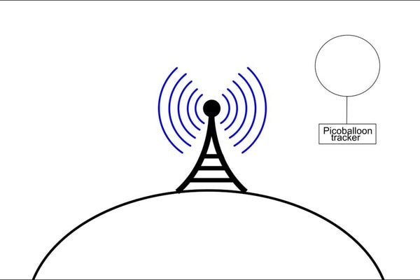
So, when building a device like this, there are many variations and choices but every tracker needs a transmitter and a power supply. Most of the trackers will likely include these components:
– a solar panel
– a battery (lipo or supercapacitor)
– a processor/microcontroller
– a GPS module
– a sensor/s (temperature, humidity, pressure, UV, solar radiation…)
– a transmitter (433MHz, LoRa, WSPR, APRS, LoRaWAN, Iridium)
As you can see, there are many sensors and transmitters that you can use. What sensors you use is up to you. It doesn’t really matter but most common are the sensors of temperature and pressure. Selecting a transmitter is much more difficult though. Every technology has some pros and cons. I won’t break it down here because that’d be a very long discussion. What’s important is that I chose LoRaWAN and I think that it’s the best (because I didn’t have a chance to test the others yet). I know that LoRaWAN has probably the best coverage though. You’re welcome to correct me in the comments.
Step 2: Needed Parts
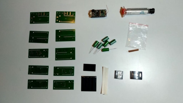
So, you’ll need these things for this project:
Ublox MAX M8Q (We didn’t use this at the end)
BME280 temperature/humidity/pressure sensor
If are launching by yourself, you also need this:
At least 0.1m3 of helium (search: “helium tank for 15 balloons”) buyed locally
Qualatex 36″ self-sealing foil balloon
Estimated project cost: 80€ (only the tracker) / 100€ (including balloon and helium)
Step 3: Recommended Tools
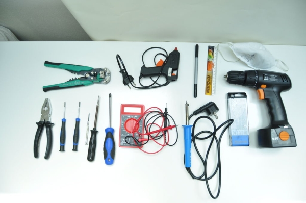
These tools could come in handy:
wire stripper
soldering iron
SMD soldering iron
pliers
screwdrivers
glue gun
multimeter
microscope
hot air gun
You’ll also need soldering paste.
Step 4: Adafruit Feather 32U4
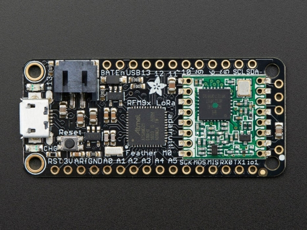
We had a hard time selecting the right microcontroller for the balloon. The Adafruit Feather turned out the best for the job. It fits all the required criteria:
1) It has all the necessary pins: SDA/SCL, RX/TX, digital, analog
2) It has the RFM95 LoRa transmitter.
3) It’s lightweight. It’s mass is only 5.5g.
4) It has very low power consumption while in sleep mode (only 30uA).
Because of this, we think that the Adafruit Feather is the best microcontroller for the job.
Step 5: PCB Design and Manufacturing
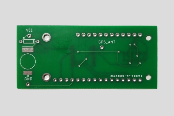
I’m truly sorry for what I’m going to tell you. We’re going to need to make a custom PCB. It’s going to be hard and frustrating, but it’s necessary, so let’s get started. Also, to understand the following text properly, you should read this awesome PCB design class by Instructables.
So, at first you will need to make a schematic. I made both the schematic and the board in EAGLE PCB design software by Autodesk. It’s free, so download it!
It was my first time designing a PCB and I can tell you that it’s all about getting hang of the Eagle interface. I designed my first board in 6 hours, but my second board took me less than an hour. Here is the result. A pretty nice schematic and a board I would say.
When you have the board file ready, you need to create the gerber files and send them to the manufacturer. I ordered my boards from jlcpcb.com but you can choose any other manufacturer you like. I set the PCB thickness to 0.8mm instead of the standard 1.6mm because the board needs to be light. You can see my settings for JLC PCB in the screenshot.
If you don’t want to download Eagle, you can just download “Ferdinand 1.0.zip” and upload it to JLC PCB.
When you order the PCBs, just sit down comfortably in your chair and wait two weeks for them to arrive. Then we can continue.
Note: You can notice that the schematic is a bit different from the actual board. That’s because I noticed that the bare BME280 IC is too hard to solder so I changed the schematic for a breakout.
Step 6: SMD Soldering
Another sad announcment: SMD soldering is not easy. Now really, it’s fricking hard. May the lord be with you. But this tutorial should help. You can solder either using a soldering iron and a solder wick, or a soldering paste and a hot air gun. Neither of these methods was convenient enough for me. But you should get it done within an hour.
Place the components either according to the silkscreen on the PCB or according to the schematic.
Step 7: Soldering

After the SMD soldering is done, the rest of the solder job is basically a piece of cake. Almost. You’ve probably soldered before and I hope you’ll want to solder again. You just need to solder the Adafruit Feather, antenas, the solar panel and the supercapacitors. Pretty straightforward I would say.
Place the components either according to the silkscreen on the PCB or according to the schematic.
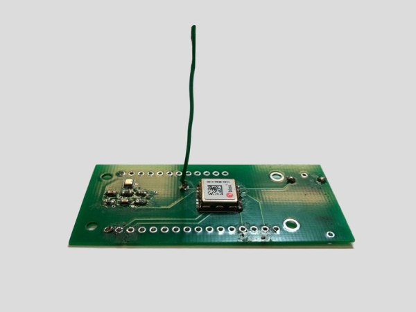
Step 8: Complete Tracker
This is how the complete tracker should look. Weird. Nice. Interesting. Those are the words that come to my mind right away. Now you just need to flash the code and test if it’s working.
Step 9: TTN Setup
The Things Network is a global city centered community LoRaWAN network. With more than 6887 gateways (receivers) up and running it’s the biggest global IoT network in the world. It uses the LoRa (Long Range) communication protocol which is generaly at frequencies 868 (Europe, Russia) or at 915MHz (USA, India). It’s most widely used by IoT devices sending short messages in cities. You can only send up to 51 bytes, but you can easily get a range from 2km to 15km. That is ideal for simple sensors or another IoT devices. And best of all, it’s free.
Now, 2-15 certainly isn’t enough, but if you get to higher ground, you should have a better connection. And our balloon will be very high. At 10km above sealevel, we should get a connection from 100km. A friend launched a HAB with LoRa 31km up in the air and he got a ping 450km away. So, that’s pretty reasonable.
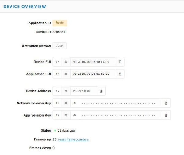
Setting up the TTN should be easy. You just need to create an account with your email and then you need to register the device. At first, you have to create an application. An application is the whole project homepage. From here you can change the decoder code, view the incoming data and add/remove devices. Just pick a name and you’re ready to go. After that is done, you’ll have to register a device in the application. You need to input the MAC adress of the Adafruit Feather (with the Feather in the packaging). Then you should set the activation method to ABP and you should disable frame counter checks. Your device should now be registered in the application. Copy the Device Adress, the Network Session Key and the App Session key. You’ll need them in the next step.
For a more wholesome explanation, visit this tutorial.
Step 10: Coding

The Adafruit Feather 32U4 has an ATmega32U4 AVR processor. That means that it doesn’t have a separate chip for USB communication (as Arduino UNO), the chip is included in the processor. That means that uploading to Adafruit Feather can be a bit harder compared to a typical Arduino board, but it works with Arduino IDE so if you follow this tutorial it should be fine.
After you have setup the Arduino IDE and sucessfully uploaded the “blink” sketch you can move onto the actual code. Download “LoRa_Test.ino”. Change the Device Adress, the Network Session Key and the App Session key accordingly. Upload the sketch. Go outside. Point the antenna to the city centre or in the direction of the nearest gateway. You should now see data popping up on the TTN console. If not, comment below. I don’t want to put everything that could’ve happened here, I don’t know if the Instructables server could handle such ammount of text.
Moving on. If the previous sketch works, you can download “Ferdinand_1.0.ino” and change the things you were supposed to change in the previous sketch. Now test it again.
If you’re getting some random HEX data on the TTN console, don’t worry, it’s supposed to do that. All the values are encoded in HEX. You’re going to need a different decoder code. Download “decoder.txt”. Copy it’s contents. Now go to TTN console. Go to your application/payload formats/decoder. Now remove the original decoder code and paste in yours. You should now see all the readings there.
Source: How to Make a Picoballoon
- Why would I want to build a picoballoon?
Picoballoons solve the high cost of helium required for heavy traditional HABs by weighing less than 20g. - How long can a picoballoon fly compared to a classic HAB?
A picoballoon can fly for up to a couple of months and travel tens of thousands of kilometers, whereas a classic HAB flies for up to 4 hours. - What is the estimated cost of the tracker alone?
The estimated project cost for only the tracker is 80€. - Which microcontroller was selected for this project?
The Adafruit Feather 32u4 was chosen because it is lightweight, has low power consumption in sleep mode, and includes an RFM95 LoRa transmitter. - Can I use a standard PCB thickness for this project?
No, the author set the PCB thickness to 0.8mm instead of the standard 1.6mm to keep the board light. - What communication protocol does the tracker use?
The project uses LoRaWAN, which offers the best coverage and is free to use on The Things Network. - How do I configure the device on The Things Network?
You must register the device using its MAC address, set the activation method to ABP, and disable frame counter checks. - Why was the GPS module removed from the final build?
The GPS module was removed last minute due to its high power consumption. - What tools are recommended for SMD soldering?
Recommended tools include a soldering iron, SMD soldering iron, hot air gun, soldering paste, and a microscope. - How is the data encoded when received on the TTN console?
The values are initially sent as random HEX data, requiring a specific decoder code to be pasted into the TTN application settings.