Summary of How to Make a Balancing Board System for Hip’s Muscles Exercise (BalanX)
This article describes creating a balance training system called BalanX for hip muscle rehabilitation after total hip replacement. It integrates an ESP8266 NodeMCU microcontroller with an MPU6050 gyroscope/accelerometer sensor mounted on a chest belt to track body tilt. Data is sent via serial to a Processing visual interface on a PC for real-time feedback. The author also designs and builds a custom wooden balancing board for exercise. The tutorial covers hardware assembly, Arduino programming, Processing setup, sensor calibration, and the wooden board construction. This low-cost DIY system aids muscle strengthening by providing visual feedback of body balance.
Parts used in the BalanX project:
- Arduino IDE installed on PC
- Processing IDE installed on PC
- Plastic electronic project box (85x50x21mm)
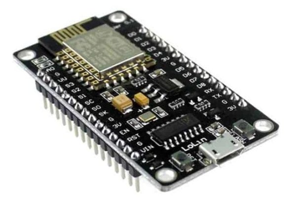
- Controller: ESP8266 NodeMCU (ESP-12E module)
- MPU6050 motion sensor module on GY-521 breakout board
- Chest belt for action cameras with adapter
- USB to microUSB cable (1 meter)
- Breadboard
- Jumper wires
- Prototyping board
- Wooden board (450x300x18mm thick)
- Two wooden planks (350x100x18mm thick)
- Two wooden laths (200x50x35mm)
- Jigsaw
- Rasp and sandpaper
- Drill with bits
- Vinyl glue
- Screwdriver
- Screws
After many happy years as a runner, two years ago I had a problem with my right hip. Unfortunately I had to undergo to total hip replacement surgery. After the operation I made a period of rehabilitation in the use of the leg muscles, through physiotherapy sessions. These sessions consisted of passive movements inducted by the physiotherapist and muscles exercises that allowed me to fully recover the joint. One of the exercises consisted of trying to balance myself with a single foot, the one of the leg affected by hip replacement, on a board that was tilting on the lateral axle only. Do you remember the crane position in Karate Kid? Ok, something similar.
The difficulty was trying to stay in static balance as much as possible and this was only achievable by activating a series of muscles that work right around the hip area, increasing their strength. The exercise involved wearing a fairly heavy bodice with a sensor positioned at the front, right on the sternum which, connected to a PC, made it possible to control on its monitor the deviation of the axis of my body related to the vertical ideal axis. During one of these sessions I came up with the idea of trying to replicate that system, letting me to exercise at home too.
In this tutorial you will learn how to make such a system.
Supplies
This is the material/tool list:
- Arduino IDE installed on PC
- Processing IDE installed on PC
- A plastic box for electronic project (85x50x21mm)
- A controller (ESP8266 NodeMCU or any other that could be programmed with Arduino IDE and small enough to be mounted in the above plastic box)
- A MPU6050 module mounted on a GY-521
- A chest belt for action cameras with camera adapter
- An USB-microUSB cable (1m)
- A breadboard and some jumper wires for system test
- A prototyping board
- A wooden board (450x300mm with a thickness of at least 18mm)
- Two wooden planks (350x100mm same thickness 18mm)
- Two wooden laths (200x50x35mm)
- A jigsaw
- A rasp and lots of sandpaper
- A drill with bits
- Vinyl glue
- A screwdriver
- Few screws
Step 1: Starting the Project
I was recovering at home after the surgery and had a lot of free time available. At that time I had an ESP8266 NodeMCU (7 € on Ebay) on a breadboard and I was experimenting an application as oscilloscope.
My basic experiment was to generate a fixed frequency sine wave, and show the waveform on a monitor using the Arduino IDE integrated serial plotter.
ESP8266 NodeMCU (Micro Controller Unit) is an open source firmware and development kit. It includes firmware running on Espressif Systems’ ESP8266 Wi-Fi SoC and hardware based on the ESP-12E module. With a USB cable (USB-microUSB) you can connect it to a computer with Arduino IDE for programming.
Googling on Internet I found a self-balancing robot project that used an Arduino board connected to a MPU6050 mounted on a GY-521 breakout board, detecting the robot’s vertical position to maintain balance.
The MPU6050 is a 3-axis accelerometer and 3-axis gyroscope sensor. The accelerometer measures the gravitational acceleration and the gyroscope measures the rotational velocity. Additionally, this module also measures the ambient temperature. I quickly realized that the MPU6050 module was the perfect module for my needs. With just 2.5 € I bought one module on Ebay.
Looking at several tutorials about the MPU6050, I found its data sheets and a lot of information about power supply and connection as well as several Arduino sketches to handle it. The main features among others are:
- The MPU6050 needs 3.3V but a voltage regulator on the GY-521 board allows you to power it up to 5V.
- GY-521 gyroscope module communicates with ESP8266 NodeMCU via I2C serial data bus, which requires only two wires (SCL and SDA)
- To communicate with the module you could use the ESP8266 NodeMCU pins D1 and D2, that are the standard pins to use for I2C serial connection without any configuration.
- The power supply to MPU6050 was taken connecting VV and GND pins.
For more information about the MPU6050 module there is a great resource on this page in the Arduino Playground.
Step 2: Connecting ESP8266 NodeMCU to GY-521
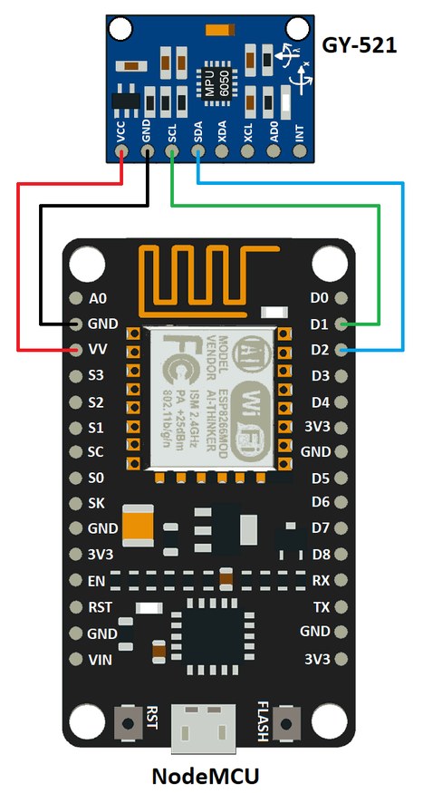
Only four wires!
Step 3: Programming ESP8266 NodeMCU
To program ESP8266 NodeMCU I’ve used Arduino IDE. Arduino is an open-source electronics platform based on easy-to-use hardware and software. The Arduino Integrated Development Environment (IDE) could be used to program different types of board including the ESP8266 NodeMCU I was playing with. Make sure you have the ESP8266 add-on installed as well as the serial interface driver. My chip was a CH340G.
For download, installation and more information about Arduino IDE please refer to this page.
Here the explanation of the simple ESP8266 NodeMCU program that connect the MPU6050 and send the values we need, to Processing:
#include <Wire.h>
const int MPU = 0x68;          // I2C address of the MPU6050
int16_t AcX, AcY, AcZ, Tmp, GyX, GyY, GyZ;
At first I’ve included the Wire library and defined the MPU6050 address. Wire Library comes with Arduino IDE and you don’t have to download anything extra. MPU6050 can have two slave addresses depending on the logic level on pin AD0 of the sensor. This pin has a built-in 4.7K pull-down resistor. Therefore, when you leave the AD0 pin unconnected, the default I2C address is ‘0x68’ and when you connect it to 3.3V, the line is pulled high and the I2C address becomes ‘0x69’.
The last line defines internal variables as integer.
void setup() {
  Wire.begin();
  Wire.beginTransmission(MPU);
  Wire.write(0x6B);            // PWR_MGMT_1 register
  Wire.write(0);               // Set to zero (wakes up the MPU-6050)
  Wire.endTransmission(true);
  delay(100);                  // Ensure gyro has enough time to power up
  Serial.begin(115200);
}
Then we have to initialize the sensor in setup. Just setting to zero the power management register it will wake up the sensor. We define also the serial communication speed at 115200.
Then, in the loop section, we define the first register to start reading and we read a total of 14 registers. We use only six of them, but eventually in Processing we will use only the first two.
void loop() {
Wire.beginTransmission(MPU);
Wire.write(0x3B); // Starting with register 0x3B (ACCEL_XOUT_H)
Wire.endTransmission(false);
Wire.requestFrom(MPU, 14, true); // Request a total of 14 registers
AcX = Wire.read() << 8 | Wire.read(); // 0x3B (ACCEL_XOUT_H) & 0x3C (ACCEL_XOUT_L)
AcY = Wire.read() << 8 | Wire.read(); // 0x3D (ACCEL_YOUT_H) & 0x3E (ACCEL_YOUT_L)
AcZ = Wire.read() << 8 | Wire.read(); // 0x3F (ACCEL_ZOUT_H) & 0x40 (ACCEL_ZOUT_L)
Tmp = Wire.read() << 8 | Wire.read(); // 0x41 (TEMP_OUT_H) & 0x42 (TEMP_OUT_L)
GyX = Wire.read() << 8 | Wire.read(); // 0x43 (GYRO_XOUT_H) & 0x44 (GYRO_XOUT_L)
GyY = Wire.read() << 8 | Wire.read(); // 0x45 (GYRO_YOUT_H) & 0x46 (GYRO_YOUT_L)
GyZ = Wire.read() << 8 | Wire.read(); // 0x47 (GYRO_ZOUT_H) & 0x48 (GYRO_ZOUT_L)
Serial.print(AcX); // Print the values to serial port (to Processing)
Serial.print("/"); // Only the first one is important. The other two
Serial.print(AcY); // could be used for future project expansion
Serial.print("/");
Serial.println(AcZ);
delay(10); // Wait and scan again
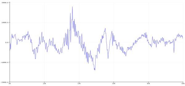
}After initialising the sensor to read 14 registers, we turn in one 16-bit integer two 8-bit values, using bitshift left (<<) 8 bits, then bitwise or (|). By connecting the ESP8266 NodeMCU and opening the serial monitor I was able to see the values coming from the MPU6050 module.
Serial.println(AcX); // Print the values to serial port (to Processing)
//Serial.print("/"); // Only the first one is important. The other two
//Serial.print(AcY); // could be used for future project expansion
//Serial.print("/");
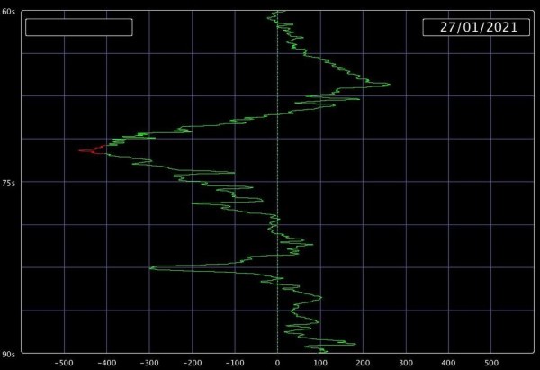
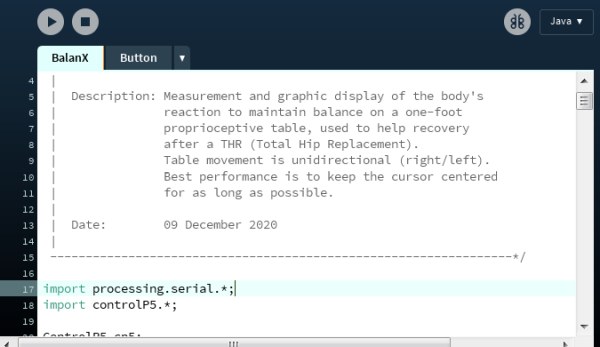
//Serial.println(AcZ);Modifying a little bit the program as shown above, sending just the first value, I’ve tried to see it using Arduino IDE serial plotter, but I realized that it was only possible to see that value with the time-base horizontally, as you can see in the picture at the page top.
In the system I used by physiotherapist I remember that the graphic line was starting from the top of the screen and going down. In this way the graphic line was the true representation of the left-right vertical deviation and more intuitive for muscles reaction. I found no way to modify the serial plotter to follow my needs nor was I able to find an easy way to show my values in real time and in a sequence top-to-bottom.
That’s why I approached Processing.
I’ve noticed that the MPU6050 module had a small offset. To get a zero value when the sensor was in the vertical position, I inserted in the Arduino sketch an offset correction.
There was a significant fluctuation and the values coming from the sensor were “nervous”, so I put in the Arduino sketch a small filter to reduce the noise and to get a smoother curve. I had to change several time the parameters to find both of them acceptable, but working on it I realized that was easier to change those parameters in the Processing sketch, avoiding the push-reset-and-flash-compile-and-transfer sequence to the ESP8266 NodeMCU board. So I moved them in Processing.
Download:
In the directory where you normally store your Arduino projects, create a new folder called BalanX. Inside this folder you download BalanX.ino (is the Arduino sketch).
Step 4: Processing
Processing is a free graphical library and flexible open-source Integrated Development Environment (IDE) built for the electronic arts, new media art, and visual design communities.
For download, installation and more information about Processing please refer to this page.
In the Processing sketch I’ve used the library ControlP5 to add a couple of text field. ControlP5 is a graphical user interface (GUI) library for Processing made by Andreas Schlegel. This library adds basic controller elements like sliders, buttons, list to a sketch. It has been around since 2005. You can download it from Github or here. After downloading und unpacking you can copy the library in the ‘libraries’ subfolder of the Processing sketches folder.
The Processing sketch is too big to explain all functions in this tutorial. Here I’ll just explain few interesting parts of it. The Processing program is necessary to visualize the values coming from MPU6050 via ESP8266 NodeMCU and its serial connection.
As I told before, after changing too much times the offset and the filter in Arduino program, I found that was easier to change those parameters in the Processing sketch, instead. But again to avoid to open and modify the file in Processing, I’ve made an external file with some parameters that are read every time the Processing sketch starts. This is the content of Parameters text file:
Adapter=0.6
Monitor=2
Filter=0.005
Adapter is the calibration of line increment to reach the bottom of the screen in 30 seconds. You have to find it through tests. It doesn’t depend only from screen height.
Monitor defines the monitor number to use. It’s set to 2, that means the second monitor will be used (if you have it, otherwise the program will switch automatically the visualization on the default monitor).
Filter is used for a small filter to smooth the nervous values coming from serial connection with MPU6050.
Now, if we start looking the Processing program we will find the settings() function. The settings() function is new with Processing 3.0. It’s not needed in most sketches. It’s only useful when it’s absolutely necessary to define the parameters to size(), or fullScreen(), with a variable.
The settings() method runs before the sketch has been set up, so other Processing functions cannot be used at that point. The settings() method runs “passively” to set a few variables, compared to the setup() command that call commands in the Processing API.
void settings() {

  // Load parameters from txt file
  String[] lines = loadStrings("Parameters.txt");
  ada = float(split(lines[0], "=")[1]);      //30s adapter
  mon = int(split(lines[1], "=")[1]);        //Monitor
  fil = float(split(lines[2], "=")[1]);      //Filter

  fullScreen(mon);                           //Monitor choice
}
Going further on in setup() function you will find the ratio calculation, for screen adjustment:
  // Screen adjustment
  int originalWidth = 1600;
  ratio = float(width) / float(originalWidth);
For practical reason I’ve used only the screen width to rescale the display. Turning to the draw() function, another interesting point is the calibration sequence with the use of millis(). This three-step sequence begins with taraStart (when the Offset button is pressed).
  // Three steps for offset calibration
  if ((millis() - startTime >= 1000) & taraStart) {
    fill(0);
    rect(450 * ratio, 350 * ratio, 400 * ratio, 200 * ratio);
    fill(255);
    textSize(30 * ratio);
    text("OFFSET\nCALIBRATION", 650 * ratio, 450 * ratio);
    startTime = millis();
    taraPrint = true;
    taraStart= false;
    offs = valueGet;
  }

  if ((millis() - startTime >= 4000) & taraPrint) {
    fill(0);
    rect(450 * ratio, 350 * ratio, 400 * ratio, 200 * ratio);
    fill(255);
    textSize(30 * ratio);
    text("CALIBRATION\nCOMPLETED", 650 * ratio, 450 * ratio);
    startTime = millis();
    taraOk = true;
    taraPrint= false;
  }

  if ((millis() - startTime >= 2000) & taraOk) {
    fill(0);
    startTime = millis();
    griglia = true;
    taraOk = false;
  }
At the end of first step the value coming from serial communication is copied in a variable (offs) that will be used as offset:
// calibration offset and max/min limitation

  valueShown = offs - valueGet;
  if (valueShown >= maxvalue * ratio) {
    valueShown = maxvalue * ratio;
  }
  if (valueShown <= minvalue * ratio) {
    valueShown = minvalue * ratio;
  }
Honestly the Processing sketch is not well structured and could be improved, but is the best I was able to write.
Download:
In the directory where you normally store your Processing projects, create a new folder called BalanX. Inside this folder you download BalanX.pde (is the main Processing sketch), Button.pde (is a class for buttons), Parameters.txt (that contains the external parameters) and BalanXpng.pde (after download rename it BalanX.pgn, please. I was not able to upload an image as a file).
Step 5: Balancing Board Design
Looking in the main online stores for a balance board, what I found was quite expensive or very different from the wooden balancing board I had in mind.
If you have already a balance board in your garage, or you have already seen a good balance board you could buy, you can skip the following steps up to step 7. But if you have to buy a new balance board and you don’t have too much money to spend, following the tutorial’s next steps it is possible to make one.
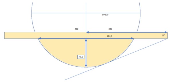
I made many different sketches and drawings with all the characteristics and dimensions of the board trying to make something similar to the original one (which I was able to measure only “on sight”). The overall size is not that rigid.
The important thing is to have something sturdy with at least 20 degrees of imbalance and big enough to put both feet on. Above is my final design.
Source: How to Make a Balancing Board System for Hip’s Muscles Exercise (BalanX)