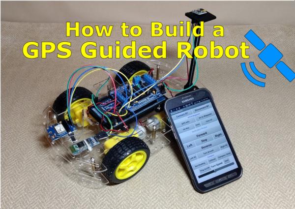
Summary of How to Build a GPS Guided Robot
The article details the construction of a GPS-guided robot controlled via a custom smartphone app. The project evolved from the author's interest in metal detecting and Arduino robotics, aiming to create an efficient, autonomous navigation system using waypoints rather than manual remote control. The build involves integrating a magnetometer for directional accuracy and a GPS module for location tracking, all managed by an Arduino Mega and Bluetooth communication.
Parts used in the GPS Guided Robot:
- Robot Platform (Car from eBay or Runt Rover)
- Arduino Mega
- L293d Adafruit or compatible motor controller
- Cellphone or Tablet
- HC-06 Bluetooth module 5 volt compatible
- HMC5883L magnetometer/ compass
- Ublox Neo 6m GPS module
- Wire in many colors
- 7.4 volt Lithium Ion Battery pack
- Ping sensor (optional)
Here is a Youtube video of me demonstrating the GPS Guided Robot. You can see that I am holding a cellphone and controlling the robot. I am at a tennis court and I am setting a Waypoint for the robot to return to. Once I position the robot where I want it to return to I, clear the GPS waypoints, Set the new waypoint, press Done when I have entered all the waypoint (in this case just one), then I press Go to Waypoint and the robot returns to the desired location, (give or take a few meters). Once I press the Go to Waypoint Button, the robot determines a course to return to the location I set. The robot constantly checks to see if it is within 0 meters of the GPS position, if it is then the App display will read “Destination Reached”. As you can see sometimes it returns to the correct location and other times it is several feet off.
How to Build a GPS Guided Robot – The Demo
P.S. The British voice is something I had to install on my cell phone and select in MIT App Inventor when programming the App.
Step 1: How to Build a GPS Guided Robot
We will start building the GPS Guided Robot in just a moment but first let me give you a little background on how this project came about. If your not interested in how the robot came into existence and why, feel free to skip to the next step.
It is probably obvious to anyone who looks at my YouTube channel that I love to metal detect, It’s also obvious that I enjoy all things Arduino and building Robots. Up until a few years ago, 2014; I had never even heard of an Arduino until I stumbled upon a YouTube Video by Bob Rudolph aka (SentryGun53). I was very impressed to say the least! Using a laptop computer, a Logitech camera, and an Arduino connected to a few servos, the Project Gun would track the person or object and shoot them with a Paintball gun. Awesome! I had to build one myself! But how was I going to do it?
I knew a little about programming, I have a degree in Computer Information Systems, but I knew nothing about microprocessors or anything about robotics. It seemed like an impossible task. Eventually after about three months of immersing myself in Arduino YouTube video tutorials, Arduino Books, magazines; I finally started to build my own project sentry gun and it worked! Much to my amazement!
Bob Rudolph’s YouTube Channel
https://www.youtube.com/user/SentryGun53
My version of the Project Sentry Gun
It wasn’t long after this that I caught the Arduino bug, I built more projects. Some were exact copies of other people’s work, some were modifications, and other were completely my own. During this time I was still metal detecting, but while metal detecting I kept thinking how cool it would be to build a metal detecting robot! I noticed that metal detecting was very robotic. Walk in a straight line, turn, move over a few feet, walk in straight line, Repeat, over and over again. But it still seemed like an impossible project, so I started looking for Videos on YouTube hoping that someone else had already built such a device. Well there were a few but most were just way to complicated or too expensive. I needed something simple, easy!
Months went by and one day I was out metal detecting when a gentleman approached me and started asking me questions, not uncommon in this hobby! But he surprised me when he said, “I can’t help but notice that what you are doing seems very repetitive, it seems like someone could build a robot to do what you are doing.” After hearing this I was determined that I would build my own metal detecting robot.
I started noticing that some people were building robotic lawnmowers, which seemed pretty simple. They were using RC remotes to control their lawnmowers, but there was one huge problem with this design. When the person would start out mowing the grass everything was great, but when they would reach the end of the lawn and turn around the person invariable got off course and would constantly have to correct their steering. Eventually, after getting off course so much they would give up trying to keep nice straight lines and just zoom all over the yard, which didn’t look very good. I also noticed that many of the commercial robotic lawn mowers operated on the same principle, zoom all over the yard in hopes that eventually all the grass would get mowed. This seemed very inefficient. I thought there had to be a better way.
When deciding to build the robot I also considered the idea that my project could have more than one application. Not only could it be used as a metal detecting robot, it could also be modified to be used as a robotic lawnmower. After all, they both would operate basically the same way.
I decided to divide the project up into smaller sections. I would need to build a platform on which to build my robot. If it was going to be used outside it would need to be very rugged. I noticed that many people who were building robot lawn mowers were using wheelchair motors. This would work on my eventual end goal but I needed something smaller for testing purposes. In case the robot got away from me I didn’t want it busting a hole in a wall or breaking furniture, so I decided I would have two separate robots. One would be a small inexpensive robot that I could quickly modify, and the other would be larger and closer to the end product, capable of outdoor navigation and able to carry a metal detector.
My goals were simple at first; build a small robot using a preexisting kit from eBay. These kits were cheap, usually less than twenty five dollars, add on an Arduino, a motor shield, a battery pack and the cost was less than fifty dollars. Next, I looked at how I was going to control the robot. I had already determined that the RC idea was out of the question so I decided to start looking for other options. Eventually, after looking at just about every option possible I decided to utilize a cell phone using Bluetooth. My main goal was to keep costs low, and I figured everyone had a cell phone. Many people even have an old spare just lying around.
Over the next few months it seemed I had to overcome more and more hurdles in order to reach my objective. First, I had to build the simple robot, attach the motor controller and Arduino; then I made the robot make simple movements without Bluetooth. Next, I had to add Bluetooth to the robot by installing a Bluetooth module and design my own App using MIT App Inventor to control the robot; moving forward, backward, left and right. In time, I would give my robot a sense of direction by adding on a magnetometer (compass) and eventually I would do the impossible task of adding GPS control.
What you are seeing in the YouTube videos are months, and months of hard work. I continue to tinker around with the design, adding features here and there. I’ve finally reached a point that I can longer spend as much time as I would like to develop this idea. So, I am turning it over to you and everyone else on the internet to see what everyone can do with it. It’s my desire to see lots of copy cats and tinkering with this project. I’m sure I will leave something out so please be sure to post a message on YouTube or Instructables so that I can document the build content better. The code is documented pretty well, I think! The code is commented so that pin hookups to the Arduino and corresponding modules should be easy. Good Luck and Thank you to the Arduino/ Robotics community!
Step 2: Build the Bluetooth Robot First
A few months ago I posted a video showing how to build a Bluetooth Robot. I would highly suggest building this robot first. “Why?”, you might ask. Excellent question! If you can build this simple Bluetooth Robot, then you can just add on to it to build the GPS Guided Robot. Once you build the Bluetooth Robot you will already have most of the things you need to build the GPS Guided Robot. You will just need to purchase a GPS module a(Ublox Neo 6M) and a magnetometer(compass) HMC5883L. Note: The Build a Bluetooth robot is a three part series, this is the first video in the series. Check out my other step by step Instructable on this project. Build a Bluetooth Robot
How to Build a Bluetooth Robot – Part 1
So check out my other Instructable on building a Bluetooth Robot and the three corresponding YouTube videos. The wiring will be the same as well, the GPS version will just require more of it. While I’m on the subject of wiring I would like to add that in most of my projects Red is VCC(+), Green is Ground(-), Yellow and Blue are communication lines. I would also add, that iit is very important to connect wires to the same locations (pins) on the Arduino as I do, and it might not be a bad idea to even use the same color wires as I have, to prevent confusion. Getting wires crossed is a common source of problems and errors.
How to Build a GPS Guided Robot – Part 1
The video above will show you everything you will need to build the GPS Guided Robot.
1. Robot Platform – Car from eBay or Runt Rover from www.servocity.com
2. Arduino Mega
3. L293d Adafruit or compatible motor controller
4. Cellphone or Tablet
5. HC-06 Bluetooth module 5 volt compatible
6. HMC5883L magnetometer/ compass
7. Ublox Neo 6m – others may work but I have not tried them
8. Wire in many colors
9. A battery pack, I use a 7.4 volt Lithium Ion Battery that feeds power to the L293d motor controller which in turn provides power to the Arduino and all other parts.
10. A ping sensor is optional, this is for collision avoidance which I have not pursued much
Step 3: Adding a Sense of Direction – a Magnetic Personality Can Be a Bad Thing
Adding a magnetometer (compass) to the robot is not optional. If your robot does not know which direction it’s pointed, then it will be very difficult for it to know which way to start it’s journey. “But doesn’t a GPS know which direction it’s headed in?” Yes, but only after it has traveled a certain direction for an extended period of time. We don’t have that kind of battery power to waste, we need a constant update on our direction so that we can create the quickest route to our destination.
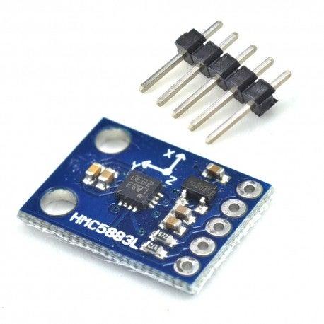
The magnetometer that I have chosen to use is the HMC5883L or should I say a cheap chinese knock-off of Adafruit’s version.Update! The particular part number is the GY-271 or the GY-273. As of November 2019 this compass is becoming hard to find unless purchased from China. If you want quality, I would suggest the Adafruit version. The magnetometer is very simple to wire up, It only has four wires VCC, Ground, and two Data lines that use I2C.
I cannot stress enough how important it is to get this part of the project Exactly Right. There are so many things that could go wrong in this part of the build. The first step in adding the compass to our robot is to solder header pins to the compass. We must make sure that our pins are not made of ferrous material, in other words no iron or anything magnetic should be anywhere near our magnetometer; otherwise, our compass readings will be inaccurate. When we tell our robot to turn right, it needs to turn exactly 90 degrees to the right, or at least very close to it.
I made a Youtube Video demonstrating this problem a while back. My magnetometers came with it’s own pin connectors that I would need to solder to the HMC5883L. After noticing that my compass readings were consistently wrong I started looking for the source of the problem. Well after a lot of aggravation I finally discovered that the pins were ferrous and throwing off my compass. Here is the Youtube video demonstrating this.
After you have determined that the connector pins are not attracted to magnets we will need to solder them to the HMC5883L. You need to be very quick about soldering to this tiny board because it can easily get overheated so work quickly.
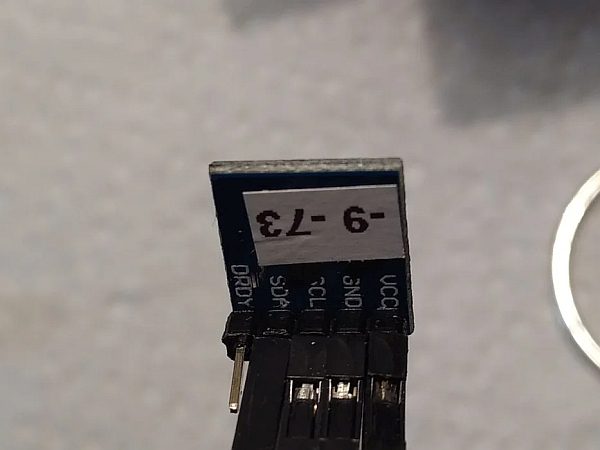
There are several different types of these magnetometers on the market but all of the ones I have seen are clearly labeled. You should see VCC(power), GND(ground), SCL, and SDA.
Step 4: A Sense of Direction – Mounting and Wiring
How to Build a GPS Guided Robot – Part 2
Once we get our magnetometer connector pins soldered we will need to mount it to the robot. It needs to be far enough away from the motors and anything else that could cause electromagnetic interference. As you can see in the videos of my robot, I have positioned the magnetometer toward the rear of the robot and approximately six inches away from the motor. One of my robots uses a 3d printed version of a GPS Folding Stand from Tinkercad, you can find a link to it here.
https://www.tinkercad.com/things/ju775hUlqeB
You can use just about anything for a mast, just make sure it is not made of metal and also be sure not to use metal screws to attach it to the mast. You can create a mast using Plastic or Wood and use zip ties or tape where needed.
Wiring up the Compass
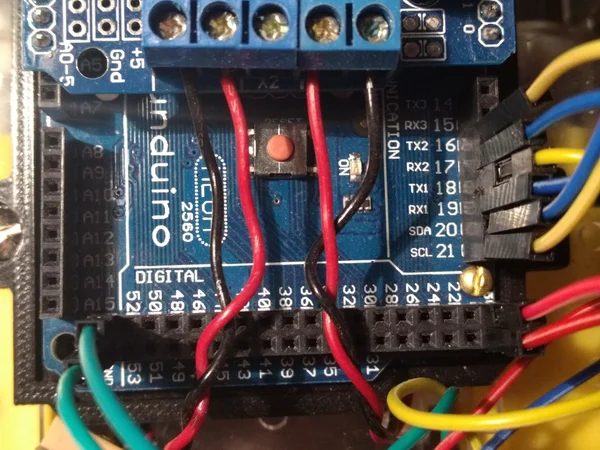
Wiring up the compass is easy, there are only only four wires. I made a YouTube video showing how to wire it up. We could choose to power the compass from the Arduino; however, the L293d Motor Control Board has several places where we could get our needed 5 volts from. There are two that are conveniently located near the left rear of our robot (assuming you mounted the mast in the same location as I did. There are two connectors here for hooking up Servo Motors, we will use one of these to supply power to our compass instead. You should see a plus “+” and a minus “-” sign near the rear of the L293d. Connect the Red VCC wire to the “+”, and the green GND to the “-” pins.
The Yellow SCL wire coming from the compass needs to go to pin 21, which is also labeled SCL. The Blue SDA wire coming from the compass needs to go to pin 20, which is also labeled SDA. That was pretty simple, Right?
VCC is Power or 5 volts – the Red wire on my example
GND is Ground – the Green wire
Hint: For the VCC and GND you will need two Female to Female Dupont wires
Then there is SCL and SDA – these are our I2C data lines
SCL is the Yellow wire in my example
SDA is the Blue wire in my example
Hint: For these you will need two Female to Male Dupont wires
Step 5: Connecting the Neo 6m GPS Module
Now we will need to wire up our GPS Module, the Ublox 6m. There are other GPS modules on the market and others may work just as well; however, this is the only one I have personally tested and I know that it works. The Ublox 6m is also very inexpensive, usually less than $15 and it can be much cheaper if your willing to wait for shipping from China.
Wiring is very easy, there are only four wires. Two wires are used for power (VCC and Ground) and two are for data lines (TX and RX). First, you may need to solder a four prong header pin to your GPS module, some already have the header pins attached depending on the one you purchased. In the YouTube video you can see that I make the following connections.
Ublox 6m GPS wire Connections
Red wire to – VCC
Yellow wire to – RX
Blue wire to – TX
Green wire to – GND
Connections to Arduino Mega
Red – VCC connects to 5 Volts – Located near pin 22 on the Arduino Mega (refer to the Video)
Green – Ground connects to Ground on the Arduino – I chose the GND pin near pin 52
Yellow – RX connects to pin 16 (TX2) on the Arduino Mega
Blue – TX connects to pin 17 (RX2) on the Arduino
Note: remember RX goes to TX and TX goes to RX when connecting serial communication lines
Step 6: A Sense of Direction – Installing the Library
There are several Libraries available for the HMC5883L magnetometer.The Library we will need is located here at Github.
https://github.com/jarzebski/Arduino-HMC5883L
I’m not saying that other libraries will not work, it’s just that this library also has a calibration program already installed which will make our lives much easier and our compass much more accurate.
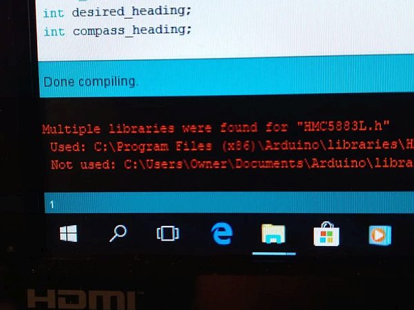
If you have installed a different library for the HMC5883L, you will probably need to uninstall or delete them; otherwise, you may get compile errors. You may also see warnings such as this one pictured above. (Photo 1)
Now, go to the link above and Download the Zip file. The second photo above shows where you need to click to download the Zip file. Remember the directory location the file is downloaded to.
Next, open the Arduino IDE and click on Sketch, Include Library, Add Zip Library (photo #3); then select the Arduino-HMC5883 Zip file that you just downloaded. The Arduino IDE will then automatically install the Library for you.
The following video will show you how to install the HMC5883L compass library and how to calibrate the compass, which is continued in the next part of this Instructable.
How to Build a GPS Guided Robot – Part 4 – The Compass
Hint: You may need to close the Arduino IDE and reopen it for the Library to work properly.
If you are unfamiliar with installing an Arduino library, here is an excellent tutorial on the subject.
https://www.arduino.cc/en/Guide/Libraries
Step 7: A Sense of Direction – Calibrating Your Compass
And now for the most fun of all, Calibrating the compass…it’s really not that much fun, but it will make our compass much more accurate.
When I first tried using the HMC5883l compass, I went through several before I found one that was fairly accurate. Afterwards, I purchased many more only to find out that none of the new compasses were accurate at all. Eventually, I discovered that the HMC5883l compass needs to be calibrated before we use it. It turns out I was just “lucky” with one of the compasses, it was fairly accurate right out of the packaging.
So, your asking, “How do I calibrate it”? You ask excellent questions!
We will need to run two different programs (sketches) to perform this task. First we will use a calibration sketch to find the X and Y offsets of our compass and then we will run another sketch program to confirm that the calibration procedure was a success, if not then we get to do it all again.
Step 1: Find the Calibration Sketch in the Examples folder of the Library we just installed, it’s located under
File | Examples | Arduino_HMC5883L_master | HMC5883L_calibrate
Step 2: Connect your Robot with the Compass attached to it and upload the Sketch to the Arduino
Step 3: Open the Serial monitor, here you will see the X and Y offsets (offX, offY) these are the only two values you need to worry about. The others you can comment out so you won’t see them, I show you how in the video.
Step 4: Slowly rotate the Robot in a circular motion making sure to keep it flat and level, keep rotating until the numbers settle down and are consistent. You may need to run this program several times by shutting down the Serial monitor and reopening it. Make sure to keep the compass as far away as possible from anything that could cause interference including anything metal or other electronics such as your computer or monitor.
Step 5: After you run the calibration test several times and have gotten consistent offset numbers, write the X and Y offset numbers down
Hint: I will usually print a label and attach it to the compass with the offset numbers so that I won’t have to run the calibration test in the future. See Photo Above.
Step 6: Next, we will run another program included with the new Library, it’s named HMC5883L_compass.
Step 7: We will first need to modify this program just a little. We will need to enter our X and Y offsets that we got in the Calibration Sketch into our code. Under Void Setup you should see the following portion of code…
// Set calibration offset. See HMC5883L_calibration.ino
compass.setOffset(0, 0);
Enter the X and Y offset numbers that you got here in place of (0,0), if it was a negative number be sure to include that. My code now looks like the following, of course your numbers will be different.
// Set calibration offset. See HMC5883L_calibration.ino
compass.setOffset(-35, -97);
Step 8: Upload the Sketch to your Arduino and open the Serial Monitor. You should see two numbers, one is labeled Heading and the other Degrees. Degrees is the one we are concerned about.
Step 9: Rotate the Robot until the Serial Monitor output reads 0 Degrees. Place a piece of tape or a card down next to the tires of the robot so that you can remember the orientation of the Robot car. Now, rotate the Robot in the opposite direction and align the tires with the Tape. The Serial monitor should read 180 degrees, or very close to it. Anything less than five degrees, I would consider a success!
Step 10: Rinse and Repeat. If your compass is off by more than 10 degrees, make sure the compass is aligned with the car as perfectly as you can. Also, run the calibration test and see if the X and Y offsets are correct. Make sure that there is nothing metalic near the compass (screws, electronics). If all else fails, try a different compass; however, this is probably not the problem.
Not seeing any data coming from your compass?
If you are having a situation where you are not seeing any data coming from the compass, the compass and Arduino may not be talking to each other The data pins (SCL, SDA) could be reversed, making a bad connection, or the address of your compass may be different than most. Usually it is “0x1E”. You see the compass uses I2C to communicate with the Arduino. You can have multiple I2C devices hooked up to the Arduino, so each one is given it’s own special “address”. If your compass is not working, check your wiring first (this is the most likely) then you may need to run an I2C scanning program to find the address of your compass.
How to Build a GPS Guided Robot – Part 3 – The Pitfalls
In this video I show you some of the pitfalls and things to watch out for when building the robot, I also show you why we need to calibrate our compass.
Step 8: Download the App
How to Build a GPS Guided Robot – Part 5
In this video I show you how the app works.
How to Build a GPS Guided Robot – Part 5a
In this video I show you step by step how to install the App, I added some more details that I may have not explained well enough in the previous video.
Step 1) There are two apps you will need to download. If you haven’t already done so you will need the MIT AI2 Companion App. It’s free on the Google Play Store, just search for “MIT App Inventor” and Install it on your phone or tablet.
Step 2) If you haven’t already got an MIT App Inventor account you will need to create one. It’s free, just google MIT App Inventor 2 and sign up. You will need to have a Google account to sign up for it.
Step 3) After creating an account, go to the App Inventor website using your computer http://ai2.appinventor.mit.edu and search the Gallery for the GPS Guided Robot app I created. You can search for it by keyword, “GPS Guided Robot” in the search box. Now click “Open the App” and it will save a copy of the App in your “My Projects Folder”. Now let’s install it on your Phone or Tablet. The App should open automatically when you clicked on it; otherwise, you should see it in your apps folder when you click on “Projects” from the App Inventor drop down menu.
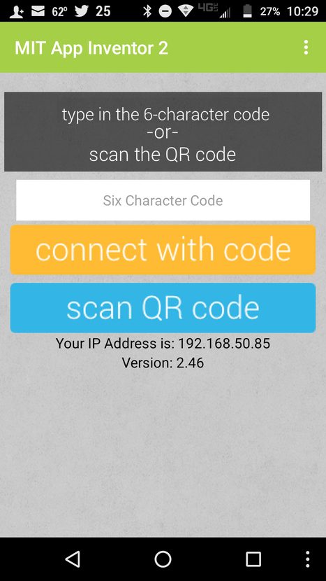
Step 4) Build the Code. In this step, MIT App Inventor will take the App and compile the source code and install it on your phone. Click on “Build” from the drop down menu on the MIT App Inventor website, next select App (provide QR code for) .apk. This will compile the App, it may take several minutes for it to do this, so be patient. When it is finished you will see a Barcode displayed in a window.
Step 5) You will need to install the app to your phone or tablet, we do this by starting the AI2 Companion that we downloaded to our phone in Step 1. Open the app and press “Scan QR Code”. Immediately a camera app will open, point it toward the barcode and hold it steady until it focuses on the barcode.
Step 6) After the barcode has been read the app will start to install on your phone, it may ask for permission to install. It should say something like”Unknown Sources” and “One time permission” to install the program. Select this and the App will install to your phone.
Step 9: Download the Arduino Code
Now we need to download the code and install to the Arduino Mega.
First we need to go to the Github website and download the code, here is a link to the website. https://github.com/mkconer/GPSRobot
I assume here that you are familiar with installing Arduino Sketches, if not I would refer you to YouTube and searching for it, or going to the official Arduino website for more information. After downloading the Arduino code from Github, we will need to make sure we have all of the necessary Libraries installed. I go over this in the following video.
Here is a list of the libraries you will need. If these Libraries are not installed, you will have compile errors when trying to Compile/ or Verify the code.
These Libraries should already be included in the Arduino IDE and you should not need to download them:
The Wire Library
The I2Cdev Library
The Servo Library
The Software Serial Library
The following Libraries are not included in the Arduino IDE and you will need to download them:
The AFMotor Library – the Adafruit Motor Shield Library ver. 1
You will probably need to download this Library from Adafruit’s website, I can’t remember but I don’t think it is standard in the Arduino IDE. If this is not correct please let me know. Here is a link to the website library.
https://learn.adafruit.com/adafruit-motor-shield/l…
The HMC5883L Library – We talked about how to install this Library for the compass in the previous steps – you can download it from Github @ https://github.com/jarzebski/Arduino-HMC5883L
The TinyGPS++ Library – You can download it from here – http://arduiniana.org/libraries/tinygpsplus/
If you are receiving any kind of compile errors it is most likely because one of these libraries have not been installed. Also, as I mentioned before, make sure no other hmc5883l compass library is installed other than the one I suggested.
I made a video explaining a little about how the code works. Unfortunately the audio is not the best in the world, there is some lag and it’s a little choppy sounding. Most of the code is commented pretty well and you can probably figure out most of what is going on just by looking at the comments in the code.
One major thing to remember is that it is important to enter the Compass X and Y offsets from the compass calibration into the code before uploading to your Arduino Mega; otherwise, the compass will be inaccurate.
How to Build a GPS Guided Robot – Part 6 – The Code and how it works.
Ok, I think that is all. If I have left anything out let me know by either leaving a message here or on YouTube.
I should mention this is probably not the kind of a project for a first time Arduino/ Robot builder; however, if I can build a Sentry Gun as my first project, then I think anyone with enough patience can build this.
Good Luck and have fun with your new robot!
Source: How to Build a GPS Guided Robot
- How do I set a waypoint for the robot?
Position the robot where you want it to return, clear existing waypoints, set the new one, press Done, and then press Go to Waypoint. - Can I use a different GPS module than the Ublox Neo 6M?
The author notes others may work but states they have only personally tested and confirmed the Ublox Neo 6M works. - Does the robot need a compass if GPS exists?
Yes, a magnetometer is required because GPS only knows direction after traveling for an extended period, whereas the compass provides constant updates. - What happens if the connector pins on the compass are ferrous?
Ferrous pins will cause inaccurate compass readings and throw off the robot's ability to turn exact degrees. - How do I calibrate the HMC5883L compass?
Run the calibration sketch in the library examples, rotate the robot in a circular motion until numbers settle, record the X and Y offsets, and enter them into the code. - What libraries must be installed before compiling the code?
You need the AFMotor Library, HMC5883L Library, TinyGPS++ Library, Wire, I2Cdev, Servo, and Software Serial libraries. - Is the ping sensor necessary for this project?
No, the ping sensor is optional and intended for collision avoidance, which the author has not pursued much. - Can I power the compass from the Arduino?
You can, but the author suggests powering it from the L293d Motor Control Board using the servo connectors near the rear. - What should I do if no data comes from the compass?
Check your wiring first, specifically ensuring SCL and SDA are not reversed, or run an I2C scanning program to find the address.