A disclaimer right up front, I didn’t shrink the remotes and that’s not a photo of my remotes through a microscope. But what I did do was shrink them down to the buttons I use the most. Not even sure what most of the others do!
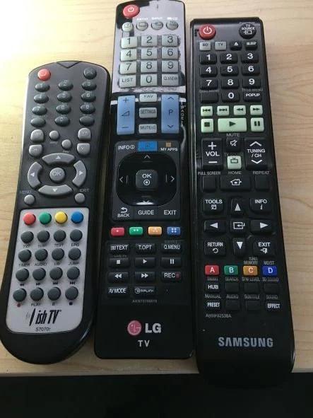
However, most of you will know what this image represents. A collection of remotes that miraculously develop flat batteries all at the same time, become chew-things for pets and small children, or get swallowed by the couch and remain hidden until you have basically disassembled it.
Add to that, trying to explain to house/pet/child sitters how to switch to [un-named] casting device/BluRay/normal TV and which volume control affects which output. Invariably you get home and they’re reading a book.
I’ve been thinking about this one for a while and finally built it, encouraged by the latest contest “Remote Control”.
Let’s begin();
Supplies
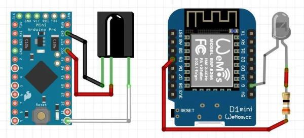
This project requires the building of 2 circuits, one can exist in breadboard form since it’s only there to read your remote codes.
Receiver (Left):
- Any arduino will do, for this instruction I’m using a Pro Micro,
- An Infrared receiver (Rx) diode. You can buy these in Rx + transmitter pairs.
Transmitter (Right):
- Any wifi ESPxx module will do, I’m using a Wemos D1 Mini,
- IR Transmitter (Tx) – Can use more than 1 in parallel to increase reliability
- A 1/4W resistor to limit the current to the LED(s), I used a 47ohm with dual leds.
At some stage you will need an enclosure for the Tx unit, near a wall socket so you can keep it powered on and line-of-sight to the target devices. An existing lamp stand works well. I used an old 50mm diameter LED ceiling light housing (nice anodised aluminium finish on the outside) and put a pair of the IR LEDs in parallel where the LED board use to be. Where and how you mount it will depend entirely on your room layout and availability of a 5v power source.
Step 1: Build the Receiver
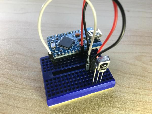
This is a reasonably simple step, but be careful to connect the receiver correctly based on the model of your unit. I have seen different pinouts for similar looking diodes and they get pretty warm when incorrectly attached (that’s not a valid test method BTW!) However, they seem to be remarkably durable..I could smell mine getting hot before realising I was trying to put the positives into the negatives pin.
As a guide (maybe) mine is the 1838T diode.
Resistance values are:
SIG->GND ~25M ohm
SIG->VCC Open
GND->SIG/VCC ~16M ohm
VCC->SIG ~22M ohm
VCC->GND Open
Step 2: Load the Rx Sketch
For this step, open the Arduino IDE and if not already installed, install the IRremote library (https://github.com/Arduino-IRremote/Arduino-IRremote) This should be listed in the IDE as the one from Armin Joachimsmeyer.
I would highly recommend reading the documentation for this library to understand the extensive capabilities of it.
Once installed, attach the arduino to your computer, set the board and port values that match your board.
Go to File->Examples->IRremote and load the ReceiveDump sketch.
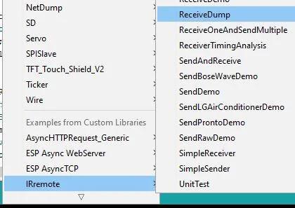
This is basically ready to go, but you might need to define the IR_RECEIVE_PIN to match whatever pin you chose to use. There are defaults if not defined in the sketch, and the library documentation has all the info. However, it’s just as easy to use your own choice:
#define IR_RECEIVE_PIN 12
Note: On A Wemos D1 I had to lookup the GPIO number because the labelling is not directly mapped to the actual GPIO number. Eg GPIO pin 12 is labelled D6
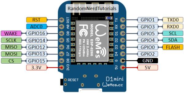
However, for this demo, I’m using a Micro so the standard pin numbering applies.
Now, if you have unplugged the Rx diode, unplug the board from the USB cable, plug the diode back in, plug the board back in and open the monitor console.
You should see some text on the screen. If it is constantly streaming data out, then check the connections and the pins for the diode. They can be very sensitive to electrical noise caused by flakey wiring on breadboards.
If you clear the monitor screen, point a remote at it and press a button, it should stream a new block of data out. The onboard LED should also react to a button press.
Not all remotes use a protocol that is supported by this particular library, but not all is lost…read on.
Step 3: Collect Your Remote Codes
This is where your choice of buttons becomes important. You will be creating a web-based UI that will be displayed on everything from laptops to mobile devices, so think of that and how many buttons you want to squeeze into that viewable space. Lets collect your first code.
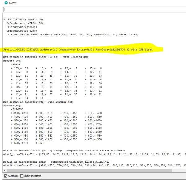
Clear the monitor output, point your remote at the Rx and press the button for about the same time you would normally. Most remotes send a lead-in code, the command code and a flag to say “here endeth my code”, a short pause, then repeats the transmit sequence. This is so the Rx does not ‘see’ a stream of data back-to-back and cannot work out what it’s saying.
With luck, you will see a line similar to that highlighted in the screenshot. It may be a different protocol(This one is “NEC”)
It may take a couple of attempts to get a properly decoded value, so if it looks like this:
Result as internal ticks (50 us) array - compensated with MARK_EXCESS_MICROS=20
uint8_t rawTicks[3] = {182,45, 11}; // Protocol=NEC Address=0xFD01 Command=0x8A Repeat gap=96850us

Result as microseconds array - compensated with MARK_EXCESS_MICROS=20
uint16_t rawData[3] = {9080,2270, 530}; // Protocol=NEC Address=0xFD01 Command=0x8A Repeat gap=96850us

uint16_t address = 0xFD01;
uint16_t command = 0x8A;
uint32_t data = 0x0;
..try again and it should produce this..
uint16_t address = 0x5343;
uint16_t command = 0x1;
uint32_t data = 0xFE015343;
..if not, look way down the end of the long lines
Result as microseconds array - compensated with MARK_EXCESS_MICROS=20
uint16_t rawData[67] = {9080,4520, 530,570, 530,620, 530,1670, 580,570, 530,570, 580,570, 530,570, 530,620,
 530,1720, 530,1670, 580,570, 530,1720, 530,1720, 530,1720, 530,1670, 580,1670, 580,570, 530,570, 580,570,
 530,1720, 530,570, 530,570, 580,570, 530,570, 580,1670, 580,1670, 580,1670, 530,570, 580,1670, 580,1670,
 580,1670, 580,1670, 530}; // Protocol=NEC Address=0x4 Command=0x8 Raw-Data=0xF708FB04 32 bits LSB first
You are looking for the “Raw-Data” value or the “uint32_t data” value.
Write/record the remote, button and code.
Do this for every button you want to use.
Step 4: Build the Transmitter
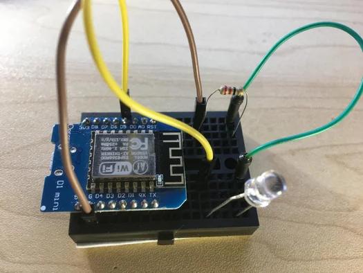
This is a very straight forward step and the Fritzing image shows the connections. The transmit IR LED is polarity sensitive (long leg on the + side) just like regular LEDs, and also need a current limiting resistor. However I have been using mine without a resistor, but running dual transmitter LEDs. I reason that because the load is being drawn by 2 LEDs and the LEDs are only lit up for mere microseconds at a time, it’ll probably be fine. Time will tell.
Step 5: Code Cutting Time!
So this is the biggest and most intense part of the whole project.
First, we need a bunch of libraries:
Installing ESP8266WebServer and ESP8266mDNS should also install several dependency modules.
If you paste:
#include <WiFiClient.h>
#include <ESP8266WebServer.h>
#include <ESP8266mDNS.h>
#include <Arduino.h>
#include "PinDefinitionsAndMore.h"
#include <IRremote.hpp>
into a new blank sketch then click the verify button (after setting the board to match the ESP model you are using) it should tell you if any are missing.
I found I had to go find the “PinsDefinitionsAndMore.h” file, but you can get a copy of it HERE , then drop it in the “src” folder of the IRremote library.
Next set the output pin of the IR diode (match the number to your build)
#define IR_SEND_PIN 12
The super-important bit:
// 2D array of devices and codes per device
uint32_t device[3][10] = {
//dishtv (on/off,ch+.ch-,v+.v-,prgm,exit,menu+,menu-)
 {0x23DCFD01, 0x6A95FD01, 0x3AC5FD01, 0x22DDFD01, 0x738CFD01, 0x7B84FD01, 0x38C7FD01,0x35CAFD01,0x35CAFD01},
//samsung (on/off,source,v+,v-)
 {0xFE015343, 0xEE115343, 0xCC335343, 0xC43B5343},
// lgtv (on/off,input,ok,sel-L,sel-R,exit)
 {0xF708FB04, 0xF40BFB04, 0xBB44FB04, 0xF807FB04, 0xF906FB04, 0xA45BFB04}
};
This is an array of arrays to store the button codes from each device. I’ve set the array size to match the number of remotes and the largest number of buttons. It pays to add the key map as comments for later edits.
This lets us use array index values in the transmit function by referencing the device[index][button index] to get the right codes.
This next section is the function that transmits the remote code using values sent to it from the HTTP webserver POST data handler. The handler has read the values received from the POST request then calls this function along with sending the device and button array index values.
// IR sender function, transmit twice which seems to be how many times it recorded on a single push
void transmit(int d, int i) {
 IrSender.sendNECRaw(device[d][i], 0);
 delayMicroseconds(96800);
// delay must be greater than 5 ms (RECORD_GAP_MICROS), otherwise the receiver sees it as one long signal
 IrSender.sendNECRaw(device[d][i], 0);
}
We send it twice using a very short delay between attempts, using the ms delay seen in the original IR capture value as a guide. Kinda like a ‘make sure you saw it’ thing. I have tested this using a single send and it seems pretty reliable.
uint16_t rawData[3] = {9080,2270, 530}; // Protocol=NEC Address=0xFD01 Command=0x8A Repeat gap=96850us
Speaking of web servers, best we create one!:
const char *ssid = "ThisIsNotMyWiFi";
const char *password = "ThisIsNotMyPassword..either";
ESP8266WebServer server ( 80 );
Obviously you should use your actual WiFi SSID and password values. You want my credit card number too? Yeah..nah!!
If your wifi router or home network has DNS capability, it would be useful to create a static IP reservation for the ESP and/or a DNS record to make it easy to remember the ESP server name on the network.
Now we build the code for the webpage, including some styling and a javascript function to handle the buttonclicks. To send the right device index number to the handler, we store the index as an easy-to-remember variable name. The first line allows for creating all the HTML, CSS and javascript code into a single variable that can be used anywhere in the sketch. It reduces a lot of Serial.print and quote escaping code.
// HTML page code, incl CSS and javascript
const char MAIN_page[] PROGMEM = R"=====(
 <!DOCTYPE html>
 <html>
  <head>
  <title>Our Remotes</title>
  <script type="text/javascript">
  var dishtv = 0;
  var samsung = 1;
  var lgtv = 2;

  function sendIR(dev,cmd){
   const xhr = new XMLHttpRequest();
   xhr.open("POST", document.location.origin + "/godata",true);
   xhr.setRequestHeader("Content-Type", "application/x-www-form-urlencoded");
   xhr.send("dev="+dev+"&cmd="+cmd);
   xhr.onreadystatechange = (e) => {
    console.log(xhr.status)
   }
  }
  </script>....
..buttons and layouts
div class="btnBig"><table width="100%" border="0"><tr>
   <td class="bigCell"><button class="btnMain" id="lgtv_onoff" onClick="sendIR(lgtv,0)">TV ON/OFF</button></td>
   <td class="smallCell"><button class="btnSub" id="lgtv_src" onClick="sendIR(lgtv,1)">INPUT</button><br>
   <button class="btnSub" id="lgtv_selLeft" onClick="sendIR(lgtv,3)" width="45%"><<</button><button class="btnSub" id="lgtv_selRight" onClick="sendIR(lgtv,4)" width="45%">>></button></td>
   <td class="smallCell"><button class="btnSub" id="lgtv_OK" onClick="sendIR(lgtv,2)" height="100%">OK</button><br><button class="btnSub" id="lgtv_Exit" onClick="sendIR(lgtv,5)" height="100%">EXIT</button></td>
   </tr></table></div><hr>
These are the buttons for the TV, and uses the onClick event to send the device name(transposed to the device id) and the button index. It uses a mix of CSS and inline styles to control the layout. By far this was the most time consuming part of checking the layout, modifying and testing the new look.
And then the rest, including the actions taken when the web servers gets a POST request…
// What do show on server root
void handleRoot() {
 server.send ( 200, "text/html", MAIN_page );
}

void handleNotFound() {
 String message = "File Not Found\n\n";
 message += "URI: ";
 message += server.uri();
 message += "\nMethod: ";
 message += ( server.method() == HTTP_GET ) ? "GET" : "POST";
 message += "\nArguments: ";
 message += server.args();
 message += "\n";
 for ( uint8_t i = 0; i < server.args(); i++ ) {
  message += " " + server.argName ( i ) + ": " + server.arg ( i ) + "\n";
 }
 server.send ( 404, "text/plain", message );
}

void setup ( void ) {
 Serial.begin ( 115200 );
 WiFi.begin ( ssid, password );
 //Serial.println ( "" );

 // Wait for connection
 while ( WiFi.status() != WL_CONNECTED ) {
  delay ( 500 );
  //Serial.print ( "." );
 }

 //Serial.println ( WiFi.localIP() );

 if ( MDNS.begin ( "esp8266" ) ) {
  Serial.println ( "MDNS responder started" );
 }

 server.on ( "/", handleRoot );
 server.on ( "/godata", []() {
  transmit(server.arg(0).toInt(),server.arg(1).toInt());
  server.send ( 200, "text/html", MAIN_page );
 } );
 server.onNotFound ( handleNotFound );
 server.begin();
 IrSender.begin();
}

void loop ( void ) {
 server.handleClient();
}
If you’ve ever set up an ESP as a web server, then parts of this will be familiar. However the extra code basically listens for a request, works out if it is a POST or GET request, handles bad URLs, extracts the values sent from the javascript XMLHTTPRequest and send the values to the IR transmit function.
The full code is attached, but it is for my remotes collection, my buttons, my design decision for the colours and layout. It’s just included to help get you started. It was many hours of minor changes and testing on different devices including phones and tablets in portrait and landscape orientation before I was happy with the look and usability. Even the top-to-bottom order was important, it matches the physical layout in the entertainment centre so it is intuitive.
I had tried the ESPAsync libraries which made the code a little simpler, but for some reason, and only on mobile devices, a single press of a button triggered 3 distinct transmits of the code approximately 1 second apart. Most annoying having the TV turn off then on again (wasn’t fast enough to catch the middle IR signal).
Step 6: Test and Verify
After all that, time to test. If you have kept the original receiver device, you can use it to verify your transmitter is sending the correct code for your button.
Use any device attached to your network, but test using your computer for debugging the code, and a mobile device for testing the layout and usability.
Open a browser and enter http://[ip address of ESP]. If you don’t know what it is, uncomment line 147, upload and restart the ESP with a monitor console open. Alternatively open your router configuration interface and check the DHCP leases, which would also be a good chance to create an IP address reservation for your ESP.
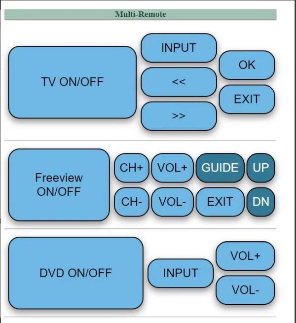
All going well, you should see this..or your version of it
If you have any Serial.write debug lines in your webserver code, you can also see that in an IDE window. You have to open a new instance of the IDE with your webserver code in one window, the receive code in the other instance. This allows you to assign different ports to each IDE instance and get the Serial output.
Note, it MUST be a separate instance, not just the other sketch opened from the existing window. Changing the port in one changes it in the other if both windows are spawned from the same instance.
You now have 3 debug options:
- The serial output of the transmit/web server
- The serial output of the receiver,
- The browser console and DOM inspector..aka Dev Tools (most browsers use F12 key to open the DevTools inspector)
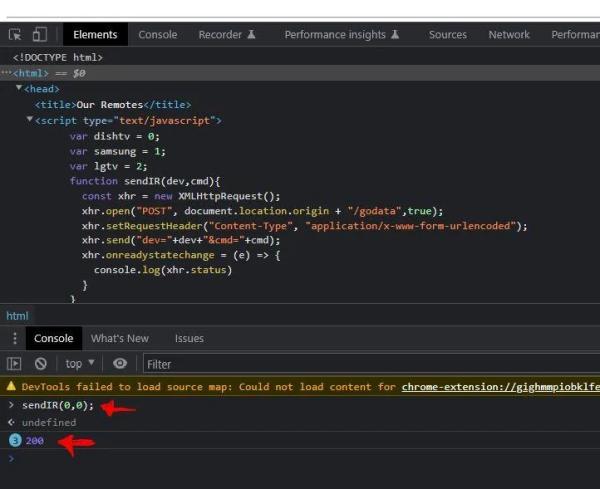
The DevTools in the browser is useful for troubleshooting the page and javascript function. You can even test the styling and dynamically change all element styles to immediately test the look before changing in the sketch.
Don’t expect the buttons to be as responsive as the physical remote. There’s a lot of processing going on in the background once a button is pressed. Buttons such as scroll, volume and channels do not have the press and hold capability.
Click a button in your new remote controller web interface and and all going well, the code for the button should print on the receiver monitor screen.
If nothing:
- Check your wiring, including the polarity of the transmit LED,
- Check your receiver is working with a remote, and the onboard LED is reacting to input
- Check for errors in the DevTools console, declarations out of place, typos, etc. Using the console, you can even trigger a POST action simply by calling the javascript function directly (see screenshot)
Step 7: Physical Placement and Testing
If you are like me, then you would have done numerous trips back and forth from the creator cave to your entertainment area, balancing the breadboards and battery pack in one hand, tablet/phone/iThing in the other to test and see it in action.
At this stage, it is best to place it somewhere in the target room with a clear line of site to the recipient devices. Mine is near a back wall about 6 metres away from the TV cabinet, and near a wall socket to plug a USB charger and cable into for power. It seems pretty reliable so far, and no issues with false triggers, not triggering or ESP stability. I had to make a couple of cosmetic changes to the buttons, such as the TV guide buttons being a slightly different colour so as to show they are logically grouped with each other (ie, the up/down arrows belong the the TV guide navigation screen)
So far, so good. It’s been 5 days and apart from forgetting that we now have the thing (“where’s that ^%$@ tv remote gone now!!”), it’s working well for us.
Step 8: Final Disclaimer
And lastly, I am not responsible for any domestic hostilities caused by misuse or abuse by competing members of the household! Some subtle negotiations will be required so she doesn’t turn the TV off because she wants to sleep and you’re up watching a late night movie.
I hope this project is of interest, maybe demonstrates a potential other project for someone, or they want to do their own version and use this as a start point. If you think it’s good enough, throw me a vote in the competition, I would really appreciate it.
Cheers.
Source: Honey I Shrunk the Remotes!
