Summary of Home Made Arduino Prototype Shield
This article guides Arduino beginners on creating a custom Prototype Shield using the photoresist method. The author modifies an EAGLE file, prints circuit patterns on transparencies, and exposes UV PCBs under fluorescent light. After developing with sodium hydroxide, copper is etched using ferric chloride. Essential tools include a hand drill for holes, ensuring a personalized and satisfying electronics project experience without purchasing pre-made shields.
Parts used in the Arduino Prototype Shield:
- Hand drill
- UV PCB
- Fluorescent lamp
- Sodium hydroxide solution
- Ferric chloride
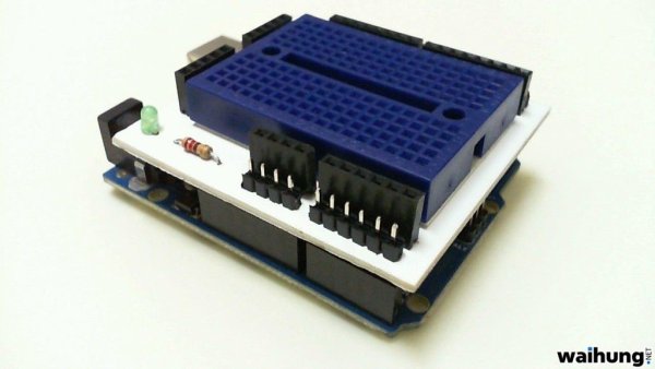
Hi. I’ve just got myself an Arduino Uno R3 and I’m really new in the world of Arduinos. There’s so much to learn and explore 🙂
One of the first shields that I’m tempted to buy is the Prototype Shield. I think building a prototype circuit right on top of the Arduino is pretty slick. So why buy it when you can make it? Trust me, it is very satisfying 🙂
The first thing that comes into mind is of course to make the PCB of the shield. The two most common ways of making your own PCB at home are the photo resist method and the toner transfer method. I’ve gone down the photo resist route because I find that the circuit produced is really sharp.
Let’s start! 🙂
Step 2: Preparing the PCB and Etching Photo Resist Layer
I found an EAGLE pcb file for the Prototype Shield from the arduino.cc website and modified it so that now it has more 5V pins and ground pins. Also added some text 🙂
Printed two of the circuits on a transparency and overlap them to get a perfect image.
Then I cut the PCB to size and used a small hand saw to cut it.
Peel off the photo resist protective sticker and lay down the transparency image on the photo resist coating.
Exposed the board under fluorescent light for about 8 minutes.
While waiting, I prepared the sodium hydroxide solution just by adding the crystals to water. Only put a small amount of it.
After 8 minutes just immerse the board into the solution and constantly agitate it. The unwanted photo resist layer should be washed off in around 10 minutes.
Next, is to etch the unwanted copper layers.
Things That You Need
To make the Arduino Prototype Shield, you need these :
1. Hand drill to drill holes in the PCB for the components to go through.
2. UV PCB
3. A fluorescent lamp to expose the PCB.
4. Sodium hydroxide solution, acting as the photo resist etchant.
5. Ferric chloride, acting as the copper etchant.
For more detail: Home Made Arduino Prototype Shield
- What are the two common ways to make your own PCB at home?
The two most common methods are the photo resist method and the toner transfer method. - How did the author prepare the transparency image?
The author printed two circuits on a transparency and overlapped them to get a perfect image. - What solution acts as the photo resist etchant?
Sodium hydroxide solution acts as the photo resist etchant. - How long should the board be exposed under fluorescent light?
The board should be exposed under fluorescent light for about 8 minutes. - What chemical is used to etch the unwanted copper layers?
Ferric chloride is used as the copper etchant. - Why did the author choose the photo resist route?
The author chose this route because they find that the circuit produced is really sharp. - How do you prepare the sodium hydroxide solution?
You prepare it by adding crystals to water and only putting a small amount of it. - What tool is needed to drill holes in the PCB for components?
A hand drill is needed to drill holes in the PCB for the components to go through.