
Summary of A high power LED flashlight
This article details the construction of a high-power LED flashlight featuring two brightness levels, current regulation, and rechargeable AA batteries. The design uses a Cree X-lamp for neutral white light, controlled by a single pushbutton via a dual flip-flop CMOS circuit. It offers approximately 3 watts at high power (2-hour runtime) and 0.3 watts at low power (20+ hour runtime), ensuring even illumination suitable for work or walking.
Parts used in the High Power LED Flashlight:
- Cree X-lamp high power LED
- Dual flip-flop IC (NXP74HC74D with Schmitt triggers)
- MOSFETs
- Bipolar transistor
- Rechargeable AA batteries
- Pushbutton switch
- 5.6 Ohm resistor
- 0.56 Ohm resistor
- 10k resistor
- 1k resistor
- Timing network capacitors
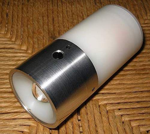
Building flashlights seems to be a fixation of mine. I built my first one at age 5 or so, and now that I’m nearing ten times that age, I’m still building flashlights. This time the project of choice was a high power LED flashlight with several interesting features:
– It uses a Cree X-lamp high power LED;
– It drives the LED at two power levels;
– The LED current is regulated;
– It uses rechargeable AA batteries;
– It has a wide beam with very even illumination, ideal as work light, reading light, or walking light;
– The light color is neutral white, not the bluish color produced by most “white” LEDs, nor the yellow/orange glow of incandescent lamps and “warm white” LEDs;
– It is controlled by a single pushbutton, through an electronic circuit;
– It fits comfortably in the hand.
At its high power setting it provides slightly over 3 watt, and a runtime of 2 hours per charge, while at low power it runs at 0.3 watt, and can operate for more than 20 hours per charge.
Let’s start with the schematic. The control circuit is permanently powered by the batteries, but consumes essentially no current while standing by. It consists of a dual flip-flop IC with some timing networks wrapped around, driving a current regulator that has two selectable current levels.
When inserting the batteries, the time delay circuit at pin 1 of the flip-flop IC first holds down that pin, causing the upper flip-flop to come up in a defined condition, with pin 5 at logic low. This in turn applies a “clear” signal to the lower flip-flop, so this one also comes up in a defined state. The MOSFETs don’t get any bias. The capacitor at pin 1 soon charges up, and there is no further current drain anywhere until you press the pushbutton for the first time. The current consumed by this CMOS IC in static condition is totally negligible.
When the button is pressed, a time delay circuit performs contact debouncing, and then the upper flip-flop sees an upgoing transition at its clock input, making it change state. This will apply Vcc to the 10k resistor biasing the upper MOSFET, which will start conducting. This MOSFET forms a current regulator, together with the 5.6 Ohm resistor and the bipolar transistor. The circuit will regulate so that the bipolar transistor is just biased into conduction, which happens at roughly 0.56V. Thus the LED current will be regulated to 100mA . The 1k resistor exists only to protect the bipolar transistor from excessive base current during transient conditions.
If the pushbutton is realeased sooner than about a half second after having been pressed, the lamp stays operating in this low power setting. But if the button is kept depressed, after a bit more than half a second the voltage at pin 11 will cross the switching threshold. At that time the lower flip-flop changes state too, switching the lower MOSFET fully on. This places the combination of the 0.56 Ohm resistor and the MOSFETs RdsON in parallel with the 5.6 Ohm resistor, resulting in an effective resistance that makes the current regulator deliver a pretty precise 1 ampere to the LED.
When the button is released, the CLK inputs eventually return to logic zero, which has no effect on the flip-flops. But if the button is pressed while the lamp is on, regardless of whether that happens in high or low power, it will change the state of the upper flip-flop, switching the lamp off, and alsoclearing the lower flip-flop, thus returning the whole circuit to its default condition. The diode quick-discharges the long time delay capacitor at pin 11, so that the logic will operate reliably even if the user fiddles quickly with the button.
Note that this circuit is picky regarding the exact flavor of CMOS flip-flop chip you use. Most flip-flops require the clock signal to complete transitioning between logic levels very quickly, and they will not work in this circuit, where the clock signals come from RC time delay circuits and thus have slow rise times! If you have a look at 74HC74 data sheets from different manufacturers, you will note that a few versions have Schmitt triggers built in at the clock inputs, while most do not have these Schmitt triggers. Only versions that have these Schmitt triggers are suitable for this circuit! The NXP74HC74D specified in the diagram is fine.
The time delay circuit between pins 6 and 2 is also involved in overcoming the trouble caused by the slow clock signal. Some samples of this circuit worked without this RC delay, but others were picky. With this delay, they all work fine.
For more detail: A high power LED flashlight
- How does the flashlight control its power levels?
The circuit uses a dual flip-flop IC driven by a pushbutton; holding the button longer than half a second switches from low power (100mA) to high power (1 ampere). - What type of LED is used in this project?
A Cree X-lamp high power LED is used to produce neutral white light. - Does the circuit consume significant power when not in use?
No, the CMOS IC consumes essentially no current while standing by because the capacitor charges up and stops further drain. - Why must specific flip-flop chips be selected?
Most flip-flops require fast clock transitions, but this circuit uses slow RC time delay signals, so only versions with built-in Schmitt triggers like the NXP74HC74D will work. - What is the runtime at the low power setting?
At the low power setting of 0.3 watt, the flashlight can operate for more than 20 hours per charge. - How is the LED current regulated in the circuit?
The current regulator uses a MOSFET, a bipolar transistor, and a 5.6 Ohm resistor to maintain a precise voltage drop that sets the current level. - Can the flashlight be turned off if it is already on?
Yes, pressing the button while the lamp is on changes the state of the upper flip-flop to switch the lamp off and clear the lower flip-flop. - What happens if the button is released before half a second?
If the button is released sooner than about half a second, the lamp stays operating in the low power setting.
