Summary of Hercules: The Motion Controlled Android Robot using Arduino
The author built "Hercules," a motion-controlled robot inspired by Nokia 5800 games, using an Arduino Uno and an Android phone for Bluetooth control. Designed for the IIT Techfest 2012, the project features four geared motors for speed and torque. The modular circuit design allows easy maintenance, with components housed in custom enclosures. This low-cost solution eliminates the need for a dedicated controller, enabling any Android device to operate the robot on obstacle tracks.
Parts used in the Hercules Robot:
- Arduino Uno
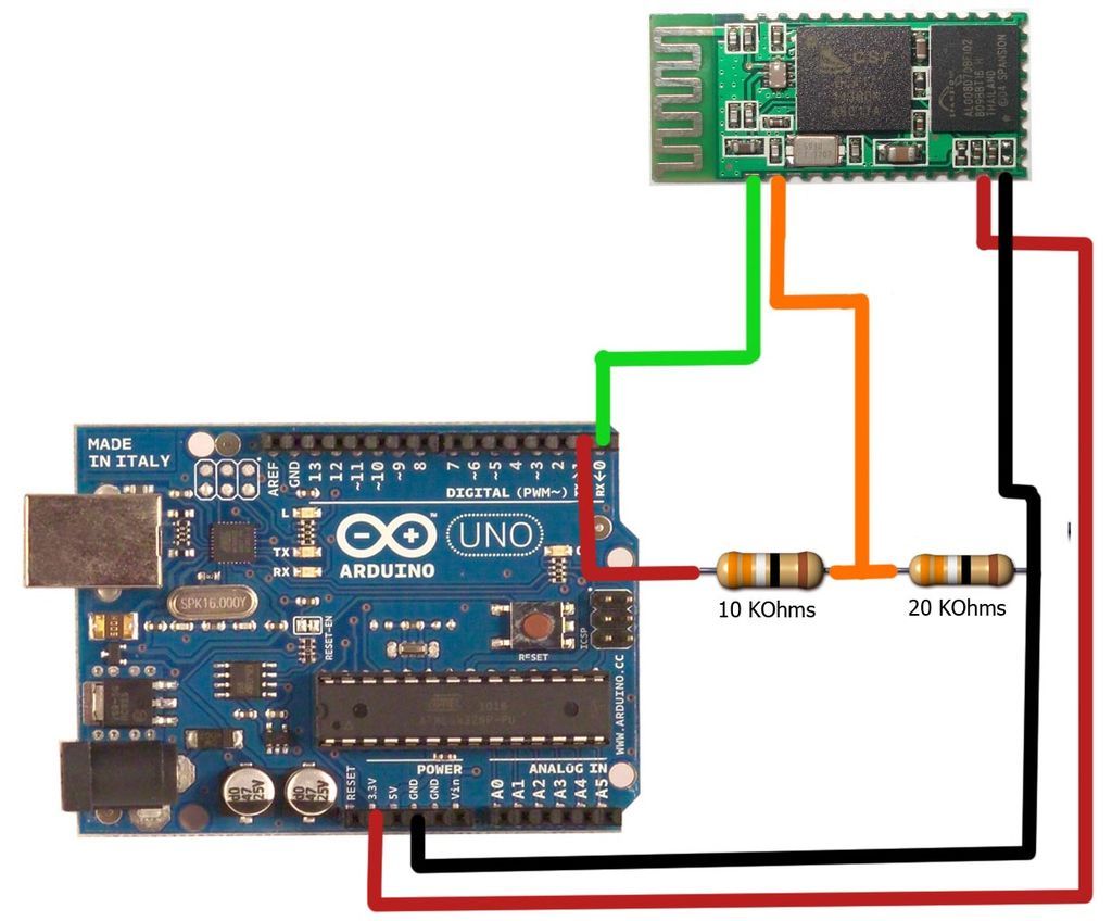
- Bluetooth Transceiver Chip (Serial Bluetooth Modem)
- L298 Dual H-Bridge IC
- 4pcs of Geared Motor
- 4pcs of wheels
- 12v 1Ah SLA Battery
- Base plate for the robot components
- 3cms x 7cms PCB
- 4pcs of Project Enclosure / boxes
- SPST Switch
- Male Header Pins (Straight)
- Wire
- Small Screws and nuts
- Resistors (1pc 10K ohms and 1pc 20k ohms)
- Android phone
- Soldering iron
- Solder
- Soldering wax
- Drill
When I was in the 8th grade, I was intrigued while playing the motion games on Nokia 5800. I was thrilled, how I could control the racing car by only tilting the phone. I used to dream of making this same car in the real world.
Now, in 11th grade ( Age 17) having got an Arduino Uno and learnt how to program it, I was able to build my “Hercules” robot.
Hercules is the name given to my motion controlled robot because of its immense torque and speed. The robot is controlled by an android phone through bluetooth. The advantage of using an android phone to control the robot, is that I can use any android phone to control it and am not confined to using only one controller for the robot. The use of an android phone as a controller, significantly reduces the cost of the project, since money is not spent in building a controller for the robot.
The Hercules was built for the 2012 Indian Institute of Technology, Mumbai’s IIT Techfest ( Asia’s largest tech festival ). The objective was to build a motion controlled robot that could race around an obstacle track.
Step 1: Step 1: Parts Needed:
For making this robot you need the following parts :
Supplies :
1. Arduino Uno.
2. Bluetooth Transceiver Chip ( Serial Bluetooth Modem).
3. L298 Dual H-Bridge IC.
4. 4pcs of Geared Motor (Specifications depend on application of the robot).
5. 4pcs of wheels.
6. 12v 1Ah SLA Battery.
7. Base plate for the robot components.
8. 3cms x 7cms PCB.
9. 4pcs of Project Enclosure / boxes .
10. SPST Switch.
11. Male Header Pins (Straight).
12. Wire.
13. Small Screws and nuts.
14. Resistors ( 1pc 10K ohms and 1pc 20k ohms).
15. Android phone.
Tools :
1. Soldering iron.
2. Solder.
3. Soldering wax.
4. Drill.
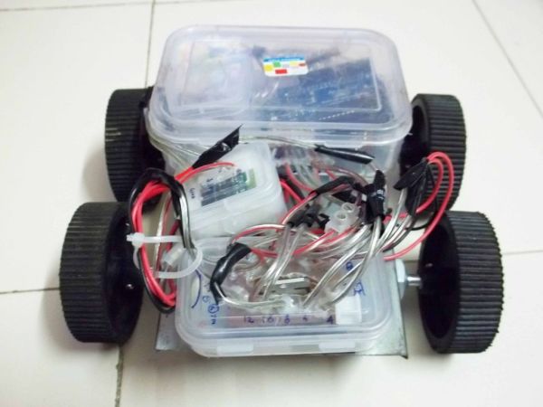
Step 2: Step 2: Chassis and wheels
The big screws on the motor make it easy to mount on chassis. The wheels slide on to the motor shaft and get screwed in place.
Connect the Left Side Motors in parallel. Connect the Right Side Motors in parallel.
After fitting the four motors and wheels, you should have something that looks like the first picture.
Step 3: Step 3: The Circuit: Arduino Box
The principle of divide and rule can be applied in every aspect of our life. This simple principle is also applied to this circuit. The circuit is divided into different boxes. This modular design makes it easy to maintain and troubleshoot the circuit. If some component burns off during the competition or when it is being run, then the corresponding module can be replaced quickly.
Arduino Box:
1. Cut the PCB using a hacksaw into 4 parts as follows: a) 2 nos. of PCB each having eight holes in length and three holes in breadth and b) 2 nos. of PCB each having six holes in length and three holes in breadth; which after assembling should look like the first picture.
2. Place the male header pins along the length of the cut PCB and solder them in place. It should look like the second picture.
3. Solder wires (approx 4 inches in length) to each of the header pins. Refer to picture 4. Now you are done with the header pins array for the arduino. By using this technique, the header pins do not come off easily from the Arduino as the force is distributed equally between the pins.
4. To prepare the project enclosure(box) for the Arduino Uno; first, temporarily place the Arduino Uno in the box. Place it in such a way that the USB port end touches the breadth of the box at one end and you can mark the part which you must cut/drill (as the USB port should stick out of breadth of the enclosure). This will help us program the Arduino board even after it is installed in the robot. After cutting/drilling the enclosure, again temporarily place the Arduino Uno in the enclosure, and apply some force making sure that the USB port sticks out of the enclosure. With the Arduino Uno in this position, you will now have to mark and drill sixteen small holes on the upper end of the enclosure’s length so that the wires coming out of the PCB circuit will pass through this enclosure (ready to be attached to some other circuit); and diagonally opposite, mark and drill twelve small holes on the lower end of the enclosure’s length so that the wires coming out of this PCB circuit will pass through the enclosure (ready to be attached to some other circuit). Note how these well planned holes help the header pin wires to come out neatly from the project enclosure box. Drill four small holes on the base of the box as per the four holes already there on the Arduino Uno so that with the help of small screws and nuts, you can permanently hold the Arduino in place.
5. Finally place the Arduino in the box and fasten it with the small screws and nut to the base of the project enclosure. Fit the header arrays on the arduino pins and drive the wires of the header pins array through the holes made in the enclosure box.
6. Now you are done with the Arduino Box. The Arduino box should look something like the first picture.
Supplies :
1. Arduino Uno.
2. Bluetooth Transceiver Chip ( Serial Bluetooth Modem).
3. L298 Dual H-Bridge IC.
4. 4pcs of Geared Motor (Specifications depend on application of the robot).
5. 4pcs of wheels.
6. 12v 1Ah SLA Battery.
7. Base plate for the robot components.
8. 3cms x 7cms PCB.
9. 4pcs of Project Enclosure / boxes .
10. SPST Switch.
11. Male Header Pins (Straight).
12. Wire.
13. Small Screws and nuts.
14. Resistors ( 1pc 10K ohms and 1pc 20k ohms).
15. Android phone.
Tools :
1. Soldering iron.
2. Solder.
3. Soldering wax.
4. Drill.
For more detail: Hercules: The Motion Controlled Android Robot using Arduino
- What is the main purpose of the Hercules robot?
The objective was to build a motion controlled robot that could race around an obstacle track. - How is the Hercules robot controlled?
The robot is controlled by an android phone through bluetooth. - Why use an android phone as a controller?
It significantly reduces the cost since money is not spent building a controller and allows any android phone to be used. - Where was this robot built for?
The Hercules was built for the 2012 Indian Institute of Technology, Mumbai's IIT Techfest. - How are the motors connected in the chassis?
The Left Side Motors are connected in parallel and the Right Side Motors are connected in parallel. - What is the benefit of the modular circuit design?
If a component burns off, the corresponding module can be replaced quickly for easy maintenance and troubleshooting. - How many parts of PCB are cut for the Arduino box?
The PCB is cut into 4 parts: two with eight holes by three holes and two with six holes by three holes. - What tool is used to mount the wheels on the motor shaft?
The big screws on the motor make it easy to mount on the chassis where wheels slide on and get screwed in place. - What specific resistors are needed for the project?
You need one 10K ohm resistor and one 20k ohm resistor. - Can the Arduino be programmed after installation?
Yes, the enclosure is drilled so the USB port sticks out, allowing programming even after the board is installed.