In this instructable, I will be showing you how to build HALO, or Handy Arduino Lamp Rev1.0.
HALO is a simple lamp, powered by Arduino Nano. It has a total footprint of about 2″ by 3″, and a weighted wood base for extreme stability. The flexible neck and 12 super-bright NeoPixels allow it to easily illuminate every detail on any surface. HALO features two push-buttons to cycle through different light modes, of which there are 15 preprogrammed. Due to the use of the Arduino Nano as the processor, there is the ability for you to reprogram it with additional features. The single potentiometer is used to adjust brightness and/or speed at which a mode is displayed. A simple metal construction makes HALO a very durable lamp, suitable for use in any workshop. Ease of use is compounded by the Nano’s onboard power regulator, so HALO can be powered through either USB or the standard 5mm barrel jack on the rear.
I hope to see many people utilizing these lamps in the near future, because there are so many possibilities that open up with this design. Please leave a vote in the Microcontroller Contest if you like this or find it useful in some way, I would really appreciate it.
Before we get into this Instructable, I would like to say a brief Thank You to all of my followers and anyone who has ever commented, favorited, or voted on any of my projects. Thanks to you guys, my Cardboard instructable became a huge success, and I am now, as of typing this reaching close to 100 followers, a big milestone in my opinion. I really appreciate all the support I get from you guys when I put up my Ible’s, and when it comes down to it, I wouldn’t be where I am today without you. With that said, thank you, everyone!
NOTE:Throughout this Instructable are phrases in bold. These are the important parts of each step, and should not be ignored.This is not me yelling or intentionally being rude, I am simply trying a new writing technique to better emphasise what needs to be done. If you don’t like it and prefer how I previously tended to write my steps, let me know in the comments, and I’ll switch back to my old style.
Step 1: Gathering Materials
How many times do I have to say it? Always have what you need, and you are guaranteed to be able to build something through to the finish.
Note: Some of these are affiliate links (marked “al”), I will get a small kickback if you buy through them, at no additional cost to you. Thank you if you do buy through the links!
Parts:
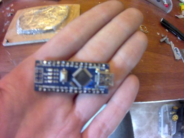
1x Arduino Nano Nano – al
1x 10k Rotary Potentiometer 5 pack 10k Potentiometers – al
1x 5mm barrel jack (mine is recycled from a fried Arduino Uno) Female Barrel Jack (5 pack) – al
2x 2-pin momentary push-buttons 10 pack SPST Pushbutton Switch – al
12x NeoPixels from a 60 LED/meter strand (any equivalent, e.g. WS2812B, will work) Adafruit NeoPixels
A sheet of 0.5 mm Aluminum
The flexible neck from an old flex lighter
The upper cover ring from a “Stick and Click” LED cabinet light LED Cabinet Light – al
A small sheet of 1/4 inch Plywood
A heavy, flat metal weight of dimensions (roughly) 1.5″ by 2.5″ by .25″
Stranded core electrical wire
Tools:
Hot Glue Gun and Glue
Soldering Iron and Solder
Cordless power drill and assorted small twist bits
X-acto knife (or a utility knife)
Wire strippers
Pliers
Wire cutters/snips
Heavy Duty Scissors
If you don’t have the flat metal weight, you also need:
1 roll of cheap solder (not the stuff you will be using for soldering) Cheap Lead-Free Solder
Alcohol Candle (or a Bunsen burner)
A small-ish hardened steel dish you don’t mind ruining (or a small crucible if you have one)
A tripod for said dish/crucible (I made mine out of 12 gauge steel wire)
A clay plant dish (one of those thingies that goes under the pot)
Some aluminum foil
NOTE: If you have a welding kit or a 3D printer, you may not need all of the tools listed here.
Step 2: Making the Weight
This is a fairly difficult step, and you must use extreme caution doing it. If you have a heavy metal weight or a flat neodymium magnet about 2.75″ by 1.75″ by 0.25″, I would recommend using that instead (and the magnet would even allow you to position the lamp sideways on metal surfaces!).
Disclaimer: I am not responsible for any injury on your part, so please use common sense.
Also, do this outside over a concrete surface that you won’t mind if it gets a bit scorched (this is just a precaution). I have no pictures for this process because a camera would have been an extra distraction that I did not need or want.
First, make a small mold out of aluminum foil or wet clay, about 2 3/4 inches by 1 3/4 inches by 1/4 inch in interior dimensions. It can be an ovoid shape like mine, or a rectangle. Use multiple layers of foil or thick layers of clay.
Place the mold in the ceramic plant dish, and fill both the mold and the tray with cold water.
Take your unlit alcohol candle/bunsen burner, and place the steel dish/crucible on the tripod so the flame will heat the center of the dish (when lit). Before lighting the burner, make sure you have at least 1 pair of pliers or metalworking tongs on hand, if not 2.
It is a good idea to be wearing leather gloves, long sleeves, long pants, closed-toe shoes, and eye protection while doing the next few steps.
Coil up and break off a bunch of the cheap solder from the spool and place it in the steel dish, then light the burner. Wait until the coil melts completely, then start feeding the rest of the solder into the dish at a moderate pace. If the solder has any rosin in it, this may spontaneously combust in the heat, producing a pale yellow flame and black smoke. Do not worry, this has happened to me multiple times and is perfectly normal.
Continue feeding the solder into the dish until the last of it is melted.
Let any flames from combusting rosin die out completely, and use the pliers/tongs to grab the dish and gently swirl the melted metal inside while carefully keeping it in the flame.
After you are sure all the solder is completely liquefied and at a good hot temperature, quickly and carefully remove it from the flame and pour it into the mold. There will be a loud hissing sound and steam as some of the water is vaporized and the rest is forced out of the mold to be replaced by molten solder.
Letting the solder cool, turn off your burner/blow out your candle and place the steel dish somewhere safe to cool. You may want to pour cold water over the cooling solder to speed the cooling and to harden it further. (The cold water makes the outside cool faster than the inside, creating internal tension that makes the metal harder and stiffer, similar to a Prince Rupert’s Drop.) You can also run water over your metal dish, but this will result in it becoming brittle, especially if done multiple times.
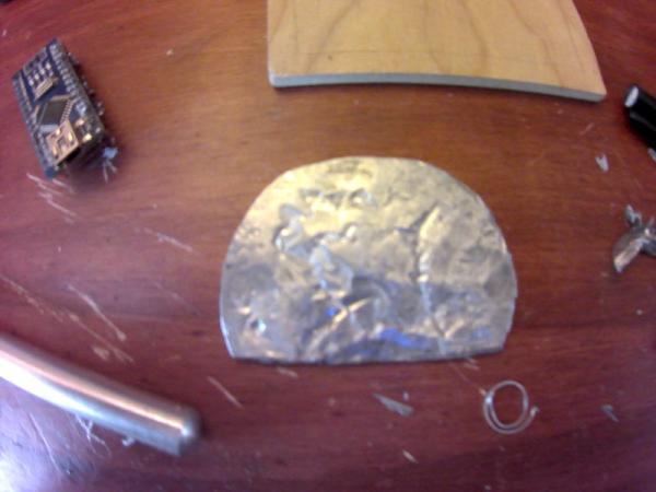
After the solder has cooled completely (about 20 minutes to be safe), remove it from the foil mold.
Mine ended up thicker on one side than the other, so I used a hammer to even it out and flatten the edges (resulting in the shape you see in the pictures). I then lightly sanded it under running water to polish it, and put it aside for later.
Step 3: Building the Electronics Housing, Step 1
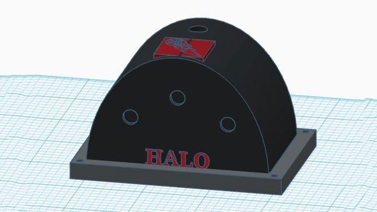
These are the parts for the shell that will house the Nano, mount the interface, and is basically what holds the HALO Lamp together. I made mine with my 0.5mm Aluminum and Hot Glue, but if you have a 3D printer (something I’ve been trying to get for my shop for a while) I made a .STL version in Tinkercad which I attached here for you to download. Since I don’t have a printer myself, I was unable to test print the model to see if everything prints properly, but I think it should be fine if you add the proper support structures in your slicer. You can also copy and edit the source file here if you need or want a slightly different design or aesthetic.
The dimensions were actually derived from the metal weight I cast for myself out of solder, not from the size of the electronics, but it turned out quite well anyway and the dimensions are pretty optimal.
The pictures depict a slightly different order of operation to what I will write here, this is because I have devised an improved method based on the results of my original method.
If you are assembling from sheet metal like I am, here is what you need to do:
Step 1: Face Plates
Cut two identical half circle-ish shapes about 1.5″ tall and 3″ wide. (I freehanded mine, so they look a bit like the front of a juke box).
In one of the two plates, drill the three holes for the buttons and potentiometer. Mine were each 1/4 inch in diameter. These can be in any layout, but I prefer my potentiometer to be slightly raised in the center, with the buttons on either side forming an isosceles’ triangle. When drilling, I always make a small pilot hole before going to the required size bit, it helps center the holes and makes them a bit cleaner.
Step 2: Arched Cover
Bend over a piece of aluminum to fit around the curve of one of the face plates, and mark the proper edge length.
Cut out a strip of this length and about 2 inches wide, and form it into an arc that matches the form of the curve of the face plates on either side.
Find the center point in the top of the curve, and drill a hole to fit the flex neck of the lighter. I offset the holetowards the rear in mine because my lamp will mostly have the neck tilted forward while in use, so I wanted to add a bit of a counterbalance to that. My flexible neck was just a bit over 1/4 of an inch in diameter, so I used a 1/4 inch bit (the largest twist bit I own that is under 3/4 of an inch) and just carefully angled and twisted the drill to ‘bore’ out the hole until the neck fit.
Now that we have the parts for the shell, the next step is to add electronics and put it together!
Step 4: Building the Electronics Housing, Step 2
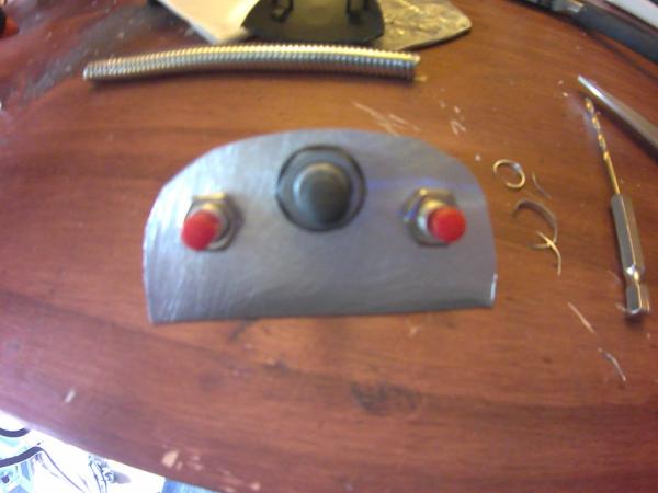
Now we add the buttons and potentiometer, and put it all together.
Step 1: Buttons and Bolts
Unscrew the hex nuts from your buttons and potentiometer. There should be a gripping ring device underneath the nut, leave this in place.
Slot each of the components through its respective hole, then screw the nuts back on to secure each in place. Tighten the nuts to the point where you are sure each component is completely secure.
Step 2. Flex Neck
Slot the flex neck through the hole in the top of the curved piece. Hot glue or weld (if you have the equipment) the neck securely in place.
If using hot glue like I am, it is a good idea to glue it with lots of glue onboth sides spread over a large area to prevent the glue from coming unstuck later.
Step 3: Shell Assembly (Does not apply to 3D printed shell)
Using either welding rod or hot glue, fasten the front and rear face plates into their respective places on the arched cover. It took me a couple tries for my glue to stick, and like before, the trick is to use lots of glue on both sides of the joint, just like the neck. The larger the area covered by the glue, the better it will stick.
Now that we have the shell, we can move on to add all of the circuitry bits.
Step 5: Adding Electronics
And here is the fun part: Soldering! In recent weeks I’ve honestly grown a bit tired of soldering, because I’ve been doing it so much lately to try and finish another project I should be putting up soon (keep an eye out for a radicalized new version of my robotic display platforms), resulting in me ruining one iron and getting another… Anyway, there isn’t much to solder here, so this should be pretty straightforward.
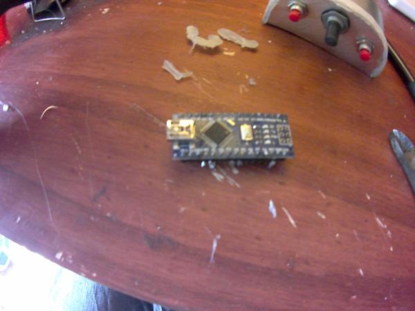
Note: If your Nano has pin headers already on it, I would recommend desoldering them for this project, they will only get in the way.
There is a diagram in the pictures above, you may follow that if you like.
Step 1: Interface
From each of the switches, solder a wire from a single pin to a side pin of the potentiometer. Solder a wire from this same side pin to a Ground pin on the Nano.
Solder a wire from the center pin of the potentiometer to A0 on the Nano.
Solder a wire from the unconnected pin of either switch to A1 on the Nano.
Solder a wire from the unconnected pin on the other switch to A2 on the Nano.
Note: It does not matter which switch is which, you can change them very easily in the code, besides the fact that one switch simply does the opposite of the other.
Cut a length of wire 4 inches longer than the flex neck, and strip both sides. Using a Sharpie, mark one side with a single line.
Solder a wire to the last unconnected side pin of the potentiometer, twist the unconnected end of this wire together with the unmarked end of the wire from the last substep.
Solder this joined end to 5V on the Nano.
Step 2: Display and Power Wires
Cut 2 lengths of wire 4 inches longer than the flex neck, and strip both ends.
Using a Sharpie, mark the ends of each wire, one wire with 2 lines, and one with 3.
Solder the wire with 2 lines to digital pin 9 on the Nano.
On your 5mm barrel jack, solder a wire from the center pin (positive) to Vin on the Nano.
Solder another wire to a side pin (ground/negative) of the barrel jack.
Twist the long wire with 3 linestogether with the wire from the side pin of the barrel jack.
Solder thesewires to the open GND pin on the Nano.
Isolate connections with electrical tape or hot glue where needed.
Step 3: Cutting Holes (only on the metal version, if you 3D printed the cover you should be fine)
Using a drill bit and an X-acto or Utility Knife, carefully make a hole in the side of the cover for the USB port of the Nano.
Make another hole about the size of the face of the barrel jack on the back of the cover, preferably nearer to the side opposite the hole for the USB port.
Step 4: Mounting Components
Feed the three long wires through the flex neck and out the other side.
Using plenty of hot glue, mount the barrel jack in place with the pins facing the top of the cover.
Again using plenty of hot glue, mount the Nano in place, with the reset button facing down and the USB port in its slot. I made a “hot glue bridge” between the barrel jack and the Nano, which makes each keep the other firmly in place.
Now we can move on to make the weighted base!
Source: HALO: Handy Arduino Lamp Rev1.0 W/NeoPixels