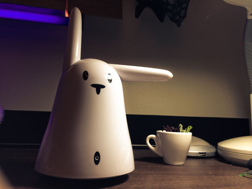
This is a Nabaztag – Armenian, apparently, for “hare”. It’s an adorable bunny rabbit packed with sensors and communication devices…. and it’s completely unusable. There’s people who wrote some interesting software to hack it, and I applaud them: however, I could never actually get my Karotz (Nabaztag’s third incarnation) through the arduous initialization. So, to gain full control over the Bunny, we’ll have to do some hardware hacking.
This Instructable takes you through the dissection of a “Nabaztag/tag” and the re-assembly of the basic bits – ears, buttons, and LEDs – with all the code you need to hack one yourself. It doesn’t have to end there, though – once you’ve embedded your own microcontroller, you’ll have the flexibility to add whatever functions and sensors you’d like.
Step 1: Materials.
A bunny.
I use a Nabaztag/tag, but either the Nabaztag or Karotz will be fine for this, as we don’t delve into the more complicated communications.
A microcontroller.
This is based on the Teensy 3.1, but virtually anything will do. In fact, if you’re familiar with BeagleBoneBlacks or RasPi’s and plan on doing advanced processing or communication (audio, bluetooth, wifi), use that, as it’ll make your bunny way more powerful.
LEDs.
I used addressable LED strip (WS2811), but plain old LEDs will work fine if you just want them to turn on and off.
H-Bridge and Breakout board.
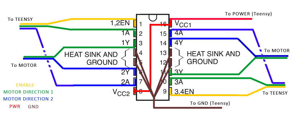
To control the motors, you need an H-Bridge chip. I use an SN754410 to control both motors. It’s also good to get a breakout board for it so you don’t have to solder directly to its pins.
https://www.sparkfun.com/products/315
Headers and sockets.
These are small and break into perfect-size pieces to fit into the existing plugs.
https://www.sparkfun.com/products/116
Hacker’s screwdriver set.
The first set of screws you need to take out need a triangle screwdriver bit; the rest are all regular Phillips screws. I highly recommend this set as an excellent addition to your kit, if you don’t have one already: http://www.ifixit.com/Store/Tools/54-Bit-Driver-K…
Colored wire.
We’re going to be connecting lots of I/O devices, so colorful wire is highly recommended to keep track of everything.
Resistors.
2 x 150 ohm
2 x 10K (or something within 5-20K range)
USB Micro cable.
Power/data to the Teensy. It’s gonna be permanent, though, so make sure you don’t mind sacrificing it for the project.
Other tools/supplies:
– Soldering kit
– Electrical tape
– Scissors/blade
– Wire cutters/strippers
– Cardboard
– Heat shrink
USB phone charger (Optional).
If you want to make your little guy portable, get one of these “lipstick” batteries. You can find them at best buy and even some drug stores, but they’re cheaper online: http://www.ianker.com/product/79AN3K-PKA
Breadboard (Optional).
If you like to test stuff out before hard-soldering anything, a prototyping board can be very handy. Line your Teensy with header pins and stick it in, then remove it when you’re ready to build it.
Software.
To use my code, you need:
– Arduino environment
– Teensyduino driver
– Adafruit Neopixel library
Step 2: Dissection.
Pop the magnetic ears off and undo the four triangle screws on Bunny’s underside; the whole thing should slide open.
All the I/O devices (except for the LEDs) are connected to the main board via quick-connect headers. Do NOT cut the wires: we’ll be attaching our own headers later, so there’s no sense in ruining the existing wires. Pry each one out of its plug; peel back the sticky gum that holds it in place with something pointy.
Keep unplugging and unscrewing until you have all the parts disconnected from the main blue board. If you want a full step-by-step, there’s one here: http://www.petertyser.com/2007/03/11/nabaztag-nab…. The next step also lists all the parts.
Step 3: Parts.
Here’s what we’re going to use:
- On/off button (on its head)
- Scroll wheel (yellow, on its butt)
- Ear motors (DC motors, which control the ears through a plastic gear box)
- Ear encoders (blue chips at ears that ‘watch’ gear teeth for positioning)
There’s some parts that you can use, but that I don’t cover in this Instructable:
- Microphone (embedded in the black base ring)
- Speaker (on its back)
- Headphone jack
- Power jack (8V, 900mA, on the bottom of the black column)
- RFID reader (smaller blue chip mounted above main board)
- WiFi antenna (green board on its back, with the thin silver wire)
And finally there’s some stuff on the main board, which I don’t think we can reuse:
- LEDs
- WiFi
- Bluetooth
Step 4: INPUT: Head Button.
We’ll start with the easiest bit: the on/off button on top of the bunny’s head. Find the white and grey wires trailing down the side. If you take some wire and tin the ends just a little bit, they’ll be perfect for sticking into the connector.
Grab your microcontroller and connect one wire to GND and one to a pin (it doesn’t matter which). This one is a digital input pin, which means we’re only looking to see if it’s HIGH or LOW. Write your own code to test it, or use mine:
https://github.com/agentcupcake/Nabaztag-Hack/blob…
This script repeatedly checks to see whether the button is being pushed, and returns a 1 or 0 in the serial monitor. The signal is being ‘debounced’ – that is, accounting for any tremors in the analog signal.
Step 5: INPUT: Scroll Wheel.
The scroll wheel is a potentiometer: it measures voltage, which changes as we rub the ‘wiper’ up and down. This is an analog input, which the Teensy will convert into a number between 0 and 1023.
Connect the:
- BROWN wire to GND
- ORANGE wire to PWR
- RED wire to an ANALOG PIN
Write some code to read the potentiometer’s values. They should be fairly steady as you “scroll” through them; for most purposes, you won’t need any signal conditioning.
https://github.com/agentcupcake/Nabaztag-Hack/blob…
This script will return the scroll value to the Serial Monitor if the head button is held.
Step 6: OUTPUT: LEDs.
Since the Nabaztag’s LEDs are embedded on the main board, we’re going to have to build our own. First, decide what LEDs you want. You can use addressable strip to make shapes (a heart? a red nose?), or string a line of basic LEDs together, or connect several LEDs to different pins and leave them as spots, like the original.
For mine, I used five pixels from an addressable strip, cut and wired to make a zig zag. The wires should connect to 5V PWR, GND, and an output pin.
If you’re using simple LEDs, use Arduino’s “Blink” as an example for writing your code. See if you can get your lights to turn on when you press the head button.
https://github.com/agentcupcake/Nabaztag-Hack/blob…
In this script, you can click the head button to turn the LEDs ON or OFF. Use the scroll wheel to pick from one of 6 colors.
Step 7: An enclosure for the LEDs.
Note that the LEDs on the main board have the cone of black plastic around them. This is to prevent the light from filling the inside of the whole rabbit, giving you a nice round spot of light instead.
To replicate this, take thin cardboard (such as from a cereal box, etc) or other stiff material, and cut a rectangle the shape of the original PCB. Include the holes so it can slide properly into place. Then, cut strips of cardboard about an inch wide and make walls to define the shape you want. It’s easier to bend cardboard if you pass a blade along the fold line first.
Tape them to the cardboard rectangle, then put the bunny back together to see how it looks through the white plastic. If the bunny’s cover doesn’t fit, trim the cardboard to fit the contours; if the light bleeds out around the edge, add electrical tape ‘flaps’ that can bend and create a seal along the edge.
The first photo is my enclosure half-finished; the second is what it looks like inside the bunny. You can see how the walls define a nice, crisp edge, and where there is no wall, the light bleeds out.
For more detail: Hack the Nabaztag using Arduino