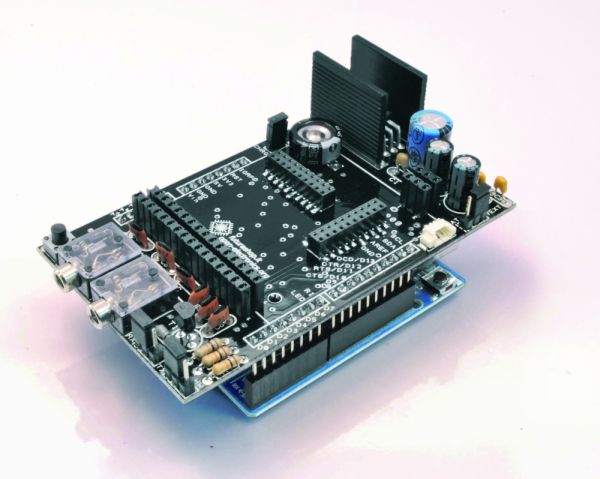
Shield for Arduino designed and based on the module GSM/GPRS SIM900 or the GSM/GPRS & GPS module SIM908, to make calls, voice and data connections via GPRS.
HARDWARE INNOVATIONS
This new version (old Arduino GSM shield) has several new hardware features, that allow maximum customization and provide many configurations.
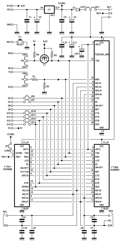
We begin with the supply circuit a simple LM7805. To work, it is necessary to provide an input voltage between 7.5V and 12V. As shown in the circuit diagram, the input voltage, after being stabilized at 5 V, is reduced to 4.3 V by using a diode and provide power to modules that need a voltage between the 3.2 and 4.8 V. During the operations such as the use of GPRS, the module absorbs a current of about 1 A, therefore it is necessary that the power source is able to provide this current intensity.
An important technical feature is the serial adapter for the communication between the GSM module and Arduino. To reduce the tension has been used a simple voltage divider, while for raising the voltage from the GSM module to Arduino we chose a MOSFET BS170.
The news that is immediately evident is the presence of two jacks for audio. With a microphone and a headset with a 3.5 mm jack (just the standard headphones for computers), you can make a voice call !!
To preserve compatibility with the Arduino Mega, we changed the selection method for the serial communication. The two different serial communication modes (hardware or software) are selectable by jumper, leaving the user the choice between the two configurations ( for serial software in this new version we adopted pins 2 and 3) or possibly use the pin to your choice with a simple wire connection. With this solution you can use the Arduino Mega using two of the four serial that it has, or possibly carry out the communication through a serial software via two pins of your choice.
Always to preserve maximum flexibility and customization, there are some pins on the back of PCB, which allow to make the connections from the Arduino digital ports and the control signals data flow (CTS, RTS) or alerts for incoming calls or unread SMS (RI). In this new version, you can then disable these connections to save inputs or outputs pins.
Comparing the new card with the previous one, you can see the presence of two connectors on the top.These additional connections allow the use of the shield also with the new small breakout for SIM900 and SIM908. The new module Simcom SIM908, is characterized by the presence of a GPS with 42 channels.
The scenery offered by this new module SIMCOM, in addition to GSM GPRS shield, it is quite remarkable: the creation of a GPS tracking device that can communicate the location via the Internet (or SMS) is now available to everyone, avoiding all the problems due to assembly and low-level programming.
C1: 100 nF
C12: 100 nF
CRCT: 0,1F
U1: 7805
T1: BS170
D1: 1N4007
P1: Microswitch
MIC: jack 3,5 mm
SPK: jack 3,5 mm
For more detail: GSM GPS shield for Arduino Board


