
Summary of GSM Based Home Security System With SMS Alert
This project is a low-cost GSM-based home security system featuring anti-theft capabilities via PIR motion detection. When the sensor detects movement, it triggers an SMS alert to a predefined mobile number while displaying real-time status on a 16x2 LCD screen. The system utilizes an Arduino for control logic and serial communication with the GSM modem to ensure reliable monitoring and theft notifications.
Parts used in the GSM Based Home Security System:
- Arduino
- GSM Modem
- PIR Motion Sensor
- 16x2 LCD
This project has GSM technology and anti-theft system using PIR motion detection. Whenever Motion is detected it sends the SMS on predefined mobile number. We have connected PIR Motion sensor with this project.
GSM based home security system with SMS alert, it uses PIR Motion Sensor, GSM Modem and 16×2 LCD is used to display system status, It Sends SMS through GSM modem that is attached to Serial Rxd and Txd Pins when motion is detected from PIR sensor, Set your mobile number inside the code in SendSMS subroutine.
Features:
1. Sends Theft Alert SMS to Given number.
2. Displays status of system on LCD.
3. Uses PIR Motion sensor
4. Low CostThis project is very useful for Monitoring home security
In this project GSM Modem, PIR Sensor, 16×2 LCD and Arduino are main parts.
You can try this project using Protius simulation. Circuit diagram, is provided with code. Download respective files.
Step 1: Make connections as per circuit diagram
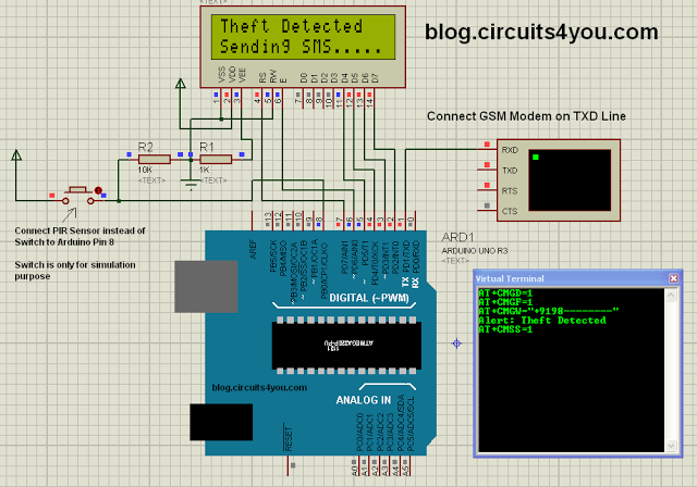
Step 2: Program the Arduino
Program the arduino using following code
/*
Home Security System with SMS Alert

 Blog.Circuits4You.com 2016

 Demonstrates the use of PIR Motion sensor and GSM Module.  The Project
 generate SMS when motion is detected on PIR Sensor

 PIR Sensor is connected to Arduino Pin 8 and GSM Module on Serial Communication
 Lines, Remove GSM Module While Programming.

  The circuit:
 * LCD RS pin to digital pin 12
 * LCD Enable pin to digital pin 11
 * LCD D4 pin to digital pin 5
 * LCD D5 pin to digital pin 4
 * LCD D6 pin to digital pin 3
 * LCD D7 pin to digital pin 2
 * LCD R/W pin to ground


 */

// include the library code:
#include <LiquidCrystal.h>

// initialize the library with the numbers of the interface pins
LiquidCrystal lcd(7, 6, 5, 4, 3, 2);

const int PIR=8;

void setup() {
  pinMode(PIR,INPUT);
  Serial.begin(9600);
  // set up the LCD's number of columns and rows:
  lcd.begin(16, 2);
}
}

void loop() {
  // Print a message to the LCD.
  lcd.setCursor(0, 0);
  lcd.print("Security System ");
  lcd.setCursor(0, 1);
  lcd.print("   Activated    ");

    if(digitalRead(PIR)==HIGH)
    {
      // Print a message to the LCD.
      lcd.setCursor(0, 0);
      lcd.print("Theft Detected  ");
      lcd.setCursor(0, 1);
      lcd.print("Sending SMS.....");

      sendSMS();
      delay(5000);
    }
}

void sendSMS()
{
     Serial.println("AT+CMGD=1");    //Delete privious sent SMS
     delay(1000);

     Serial.println("AT+CMGF=1");   //Set SMS configuration
     delay(1000);

     Serial.print("AT+CMGW=");          //Write New SMS
     Serial.write(34);                  //Double quotes ASCII Code
     Serial.print("+9198--------");         //Enter Your Mobile number
     Serial.write(34);
     Serial.println();                  //Send Crrige return
     delay(1000);

     Serial.println("Alert: Theft Detected");
     delay(1000);

     Serial.write(26); //Cntrl+Z
     delay(1000);
     delay(1000);

     Serial.println("AT+CMSS=1");      //Send SMS from memory location 1
     delay(4000);
}
Read More: GSM Based Home Security System With SMS Alert
- How does the system detect theft?
The system uses a PIR Motion Sensor connected to Arduino Pin 8 to detect motion. - Can the system send SMS alerts automatically?
Yes, when motion is detected, the GSM modem sends an SMS alert to a predefined mobile number. - What displays the system status?
A 16x2 LCD screen displays the system status such as Activated or Theft Detected. - Does this project support simulation?
Yes, you can try this project using Protius simulation with the provided circuit diagram and code. - Which pins connect the LCD to the Arduino?
LCD RS connects to pin 12, Enable to 11, D4 to 5, D5 to 4, D6 to 3, and D7 to 2. - How do you set the recipient mobile number?
You must set your mobile number inside the SendSMS subroutine within the code. - What happens if the PIR sensor reads HIGH?
If the PIR sensor reads HIGH, the system prints Theft Detected and calls the sendSMS function. - Is this considered a low-cost solution?
Yes, the article explicitly lists Low Cost as one of the main features of this project.
