This instructable was created in fulfillment of the project requirement of the Makecourse at the University of South Florida (www.makecourse.com).
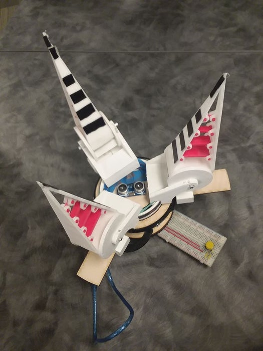
The Flex Claw is the next best project for any student, engineer, and tinkerer alike that will surely grip your audience’s attention. Run fully by an Arduino Uno, the Flex Claw is a simplified approach to a self-centering claw by only using one motor! But its capabilities are not so simple, for its claw structure is redesigned to actually flex to any shaped object it holds! Although its construction is mostly hands on, access to a 3D printer with NinjaFlex filament and PLA compatibility is necessary.
Step 1: Tools & Materials

The first step is to look over all the parts and and possibly make adjustments. For this, I highly recommend using Solidworks as it is very user-friendly once you learn where all the commands are. If your don’t already have it downloaded, be sure to check with your school or workplace for discounts or free access codes. YouTube will also be your best friend if you need more clarity on each feature. The next few steps will go over how to design the pieces for the Flex Claw with Solidworks that need to be 3D printed.
Before collecting the materials, please read through all of the steps and confirm that the one’s listed below suit your desired end product since any personalized adjustments to the size/dimensions of the pieces discussed can be made, though not recommended. The following materials are coincident with the original steps construction process.
Tools:
– 3D printable that is compatible with NinjaFleax and PLA filament.
– Plywood laser cutter (recommended for exact dimensions, but may be work around with experienced skill)
– Power drill with 3/16 drill bit
– Dremel
– Full Arduino Uno kit (wires, connection cable, etc), including a proximity sensor, LED light (with corresponding resistor), press button, and 2 stepper motors (a stronger motor may be needed depending on find results and frictional resistance).
Material:
– 12″ x 24″ x 0.125″ plywood sheet
– PVC pip 4″ Outer Diameter, about 5″ long, 0.125″ wall
– Grip tape
– 6/32″ screws 1.5″ long X 6, with respected nuts
– 0.125″ diameter Aluminum Rod, 6″ long & proper Hacksaw for future cuts
– Outlet connect with at least 2.5 Amp output (an I-Phone/I-Pad charger does work)
Step 2: The Claw: Exterior
Now that we have Solidworks, we can begin modeling the external claw design. This is encouraged to be one of the first steps since this piece needs to be 3D printed with NinjaFlex filament, which takes longer to form than most plastics and probably needs an outside source for a 3D printer that is compatible with this filament.
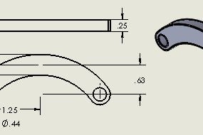
The Claw is a key feature to the project since is actually bends to the the shape of any held item. By allowing a very flexible, thin wall exterior, we can take advantage of its natural collapsibility to maximize the contact surface area for a better grip. The other side of the coin, though, is that it still needs internal rigid bridges to still maintain its structure and apply the compressible forces upon contact (step 3).
These are the pieces to make one claw, so be prepared to print 3 times this amount for 3 claws. I good tip is that we can print multiple parts at the same time as long as there’s enough room on the bed. But this also might increase the frustration is one piece goes bad during the printing process, then we would need to stop the print for the rest of the pieces too. Too many pieces on the bed could also result in the plastic layer one part hardening too much before the next layer is added (since the machine has to go around to the other parts) and causes a bend in the middle of the piece. Experience as to want your 3D printer can handle is that best thing for thing, but keep in mind that more than one part can print at a time.
Along with the solidworks part files, attached are the solidworks drawing displaying the measurements used. Although most of these lengths can be changed to better fit your accommodations, any changes will need to then be carried through to other pieces to ensure that everything fits together. So adjustments are recommended to be reserved until after you look over every step and consider the end result. Otherwise, these are the basic steps to design the intended given model.
Step 3: The Claw: Internal Bridges
Next up, the internal bridges for the claw. While the external claw design needs to be printed with NinjaFlex to allow flexibility, these bridges instead need to be printed with a PLA filament. These will be rigid and act as bones to maintain the claw’s structure as it bends and apply the compressible forces upon contact.
Along with the solidworks part files, attached are the solidworks drawing of the pieces displaying the measurements used. These are the dimensions that are compatible to the rest of the claw design so that everything fits together, so be sure that any personal adjustments to previous parts are carried through to this pieces if needed. Otherwise, these are the basic steps to design the intended given model.
(These are the pieces to make one claw, so be prepared to 3D-print 3 times this amount for 3 claws)
Step 4: The Slider
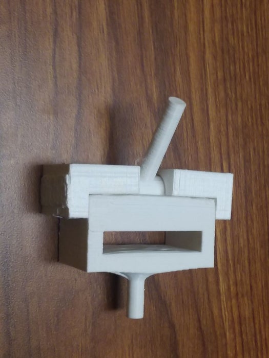
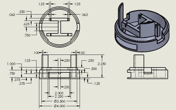
The Slider is made of 4 parts: 1 dominant slider, 1 drum with a post, and 2 “slider attachments”. With the way this is designed, the slider can fully encase the drum without restricting its ability to rotate within its groove. This also does not require screws since the attachments just pop into the main slider and over the placed drum.
Along with the solidworks part files, attached are the solidworks drawing of the pieces displaying the measurements used. These are the dimensions that are compatible to the rest of the claw design so that everything fits together, so be sure that any personal adjustments to previous parts are carried through to this pieces if needed.
(These are the pieces to make one claw, so be prepared to 3D-print 3 times this amount for 3 claws)
Step 5: The Drum & Harness
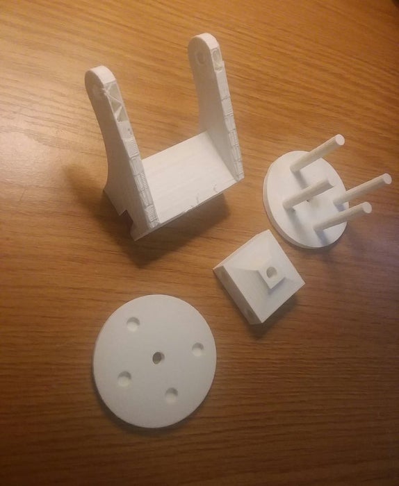
The drum and drum harness are the middlemen to connect the claw to the slider and allows it to rotate forward as the sliders move outward. Unlike the previous parts than must be 3D printed, these pieces can be made worked around by instead using wood and aluminum rods. But it’s not recommended since these do have exact measurements that let the other pieces connect all together, especially the harness that has a bottom groove that should fit the thickness and curvature of the PVC pipe rim. Please check this parameter to the PVC pipe you already have or take note of it to find one that fits.
In a future step, we will assemble these parts so that the Drum connector’s bottom hole fits with the slider drum’s shaft and that the wider pair of posts on the DrumHalf fit through the through wholes at the base of the Claw exterior. With that being said, these are the dimensions that are compatible to the rest of the claw design so that everything fits together, so be sure that any personal adjustments to previous parts are carried through to this pieces if needed.
(These are the pieces to make one claw, so be prepared to 3D-print 3 times this amount for 3 claws)
Step 6: Pinion & Ring Gear
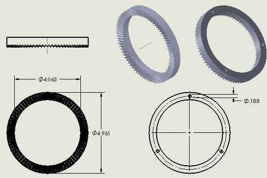
This is where the power comes in. Both the Gear pinion and ring gear should not be changed for 3D printing since they are very particular. The pinion hub has a whole fit only for the basic stepper motor mentioned. If another motor wants to be used with different shaft dimensions, then this can be adjusted for in the solid works file. For this model, 2 stepper motors are being used, so be sure to print 2 pinions.
Along with the solidworks part files, attached are the solidworks drawing of the pieces displaying the measurements used. These are the dimensions that are compatible to the rest of the claw design so that everything fits together, so be sure that any personal adjustments to previous parts are carried through to this pieces if needed.
Step 7: Radial Arms & Carousel
The carousel later is placed over the ring gear and with rotate the radius link towards and away from the slider, pushing it back and forwards. Though this is a simple design, the carousel is not recommended to be replaced by wood and loosely supported aluminum rods since the whole piece should be sturdy enough to rotate around the PVC pipe without wiggling. In total, 3 radius links are needed.
Along with the solidworks part files, attached are the solidworks drawing of the pieces displaying the measurements used. These are the dimensions that are compatible to the rest of the claw design so that everything fits together, so be sure that any personal adjustments to previous parts are carried through to this pieces if needed.
Step 8: Base Motor Box
Step 9: Branching Slider Rails
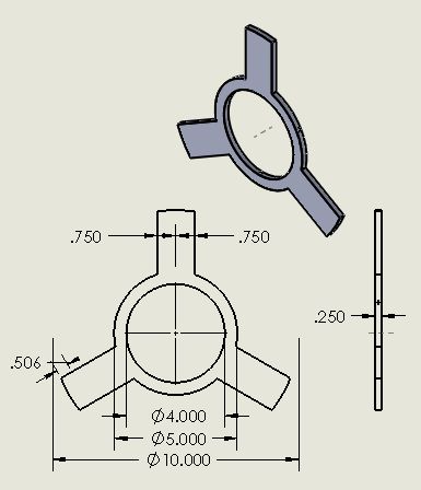
This ring will be drilled into the PVC pipe to be a stable as possible for the sliders to slide across. This piece is usually too big to be 3D printed, so I highly recommend getting access to a wood laser cutter or developing your skills with round edges in the wood shop. With this, the thickness can vary to better fit into the sliders, but make sure to still leave some wiggle room. In a later step, we will go over the best ways to secure this onto the structure.
Along with the solidworks part files, attached are the solidworks drawing of the pieces displaying the measurements used. These are the dimensions that are compatible to the rest of the claw design so that everything fits together, so be sure that any personal adjustments to previous parts are carried through to this pieces if needed.
Source: Flex Claw