Summary of Fish Sensing
The author built a capacitive sensor using a Lilypad Arduino to create a fishing game. The project involved constructing a circuit where a hand and conductive material form a capacitor, measuring discharge time to detect proximity. Challenges included securing connections and preventing short circuits with alligator clips. The code was modified to map sensor values to four colored LEDs (blue, green, yellow, red), which light up sequentially as the user gets closer to the sensor.
Parts used in the Capacitive Sensor Fishing Game:
- Lilypad Arduino
- Resistor
- Alligator clips (white, yellow, black)
- Conductive material (rectangular piece)
- LEDs (Red, Yellow, Green, Blue)
- Wires for connections
Overview
Once again, my project was motivated by my curiosity to explore interesting and unfamiliar territory. I decided to see if I could make my own capacitive sensor and then use it in a project of some sort. After numerous fiascoes with Arduino and computers, I was able to get the capacitive sensor to work and then implemented it into a fishing game. It was a highly frustrating but really fun project to do.
Right above is the circuit diagram for a simple capacitive sensor. The human’s hand and a rectangular piece of conductive material form a capacitor. The output the measures the time it takes for that capacitor to discharge. The closer the hand and coductive material are together, the longer it takes to discharge. Also, the higher the resistor between pins A & B, the more sensitive the sensor is.
The picture on the right shows the actual sensor I built. The white alligator clips connect pins A and B together through a resistor. The yellow aligator clip is the output sensor connected to one half of the capacitor. The black alligator clip is ground and is held by the human user.
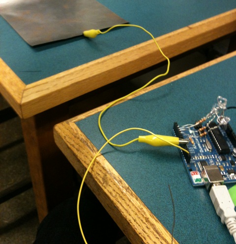
The major problems I had with the sensor was the connections. At first, I just wrapped the resistor through the actual holes in the Lilypad, but it was very wiggly and not secure at all. The alligator clips work better but they tend to disconnect from the Lilypad, or touch each other when they are close, causing a short circuit.
Coding
My next big step was to modify the code. Now that the sensor worked, I wanted to use it to light up LEDs. There are three sets of code that had to be added to the capacitive sensor sample code that we were given.

This bit of code is put under the void setup() section (Serial.begin(9600) is already in the sample code). Basically, it is naming pins 2-5 as output pins for my LEDs. Pins are automatically inputs so you need to declare them as outputs. You can have as little or as many as you want; I used four pins because I had four colours of LEDs.

This next bit of code is under the void setup() section (sensorValue=mysensor.capsense(30) is already in the sample code). This is used to limit the numbers that the capacitive sensor was showing in the serial monitor, because of too much fluctuation. So anything less than 100 becomes 0 and anything more than 1275 becomes 1275.

This last bit of code is also under the void setup() section. It is pretty easy to understand, just very annoying to write up. This is what controls which LEDs light up at which level of distance.
The first if;else phrase controls pin 2 (red LED). When the sensor values (that have been simplified to (100-1275) read 500 or more, the red LED goes on. If the value is less than 500, the red LED is off.
The second if;else phrase controls pin 3 (yellow LED). When the sensor values read 200 or more, the yellow LED goes on. If the value is less than 200, the yellow LED is off.
The next if;else phrase controls pin 4 (green LED). When the sensor values read 150 or more, the green LED goes on. If the value is less than 150, the green LED is off.
The last if;else phrase controls pin 5 (blue LED). When the sensor values read 100 or more, the blue LED goes on. If the value is less than 100, the blue LED is off.
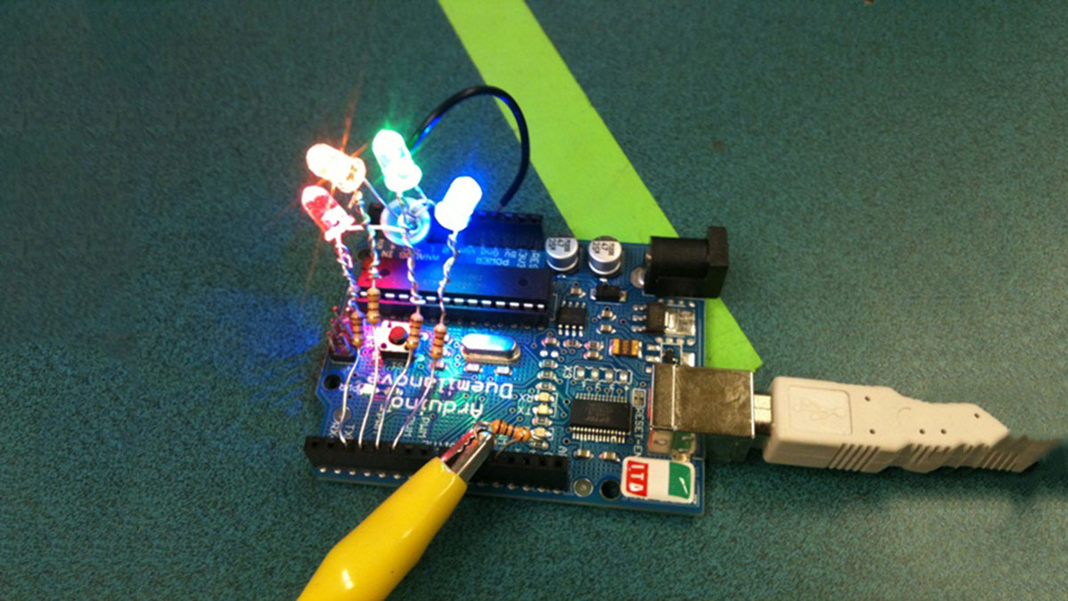
In short, the LEDs light up in this order as you get closer: blue, green, yellow, red.
The moment each LED turns on can be changed by messing around with the sensorValues. It all depends on how you want to use the sensor.
For more detail: Fish Sensing
-
How does the capacitive sensor work?
The human hand and a rectangular piece of conductive material form a capacitor, and the output measures the time it takes for that capacitor to discharge. -
What happens when the hand gets closer to the conductive material?
The time it takes for the capacitor to discharge becomes longer. -
Which component makes the sensor more sensitive?
A higher resistor between pins A and B increases the sensitivity of the sensor. -
What problems did the author face with the sensor connections?
The initial wrapping method was wiggly and insecure, while alligator clips tended to disconnect or touch each other causing short circuits. -
How many LED colors were used in the project?
Four colors of LEDs were used: red, yellow, green, and blue. -
In what order do the LEDs light up as you get closer?
The LEDs light up in this order: blue, green, yellow, and then red. -
Why was the sensor value range limited in the code?
The numbers were limited because there was too much fluctuation in the serial monitor readings. -
Can the moment each LED turns on be changed?
Yes, the moment each LED turns on can be changed by adjusting the sensorValues in the code.