In this Instructable I will show you how I made my PCB Farkle Game! Farkle, also known as 10000, Zilch, 6 Dice, and Ten Thousand, is a fun and challenging dice game with multiple variations and scoring options. I first got the inspiration from my twin brother, Sunyecz06’s Liar’s Dice PCB game in which he utilized a MAX7219 chip to “roll” 5 electronic LED dice. I thought his final product was awesome and wanted to create something utilizing similar components. Additionally, growing up, my family and I played the traditional Farkle game (with 6 dice, pen, and paper) quite a bit and we always had fun playing it, especially time’s when someone would actually “Farkle” during gameplay and we’d all shout “FAARRKKLEE!”
At some point during quarantine, I was looking for different games to play and I remembered Farkle. It was only a few turns in that the excitement I had as a kid was rekindled. Shortly after that, my tinkering wheels started turning and I thought about designing a homemade portable Farkle game that could incorporate multiple players and keep score for us. Additionally, I could use the same MAX7219 chips that my brother used to drive 6 electronic LED dice needed for the game!
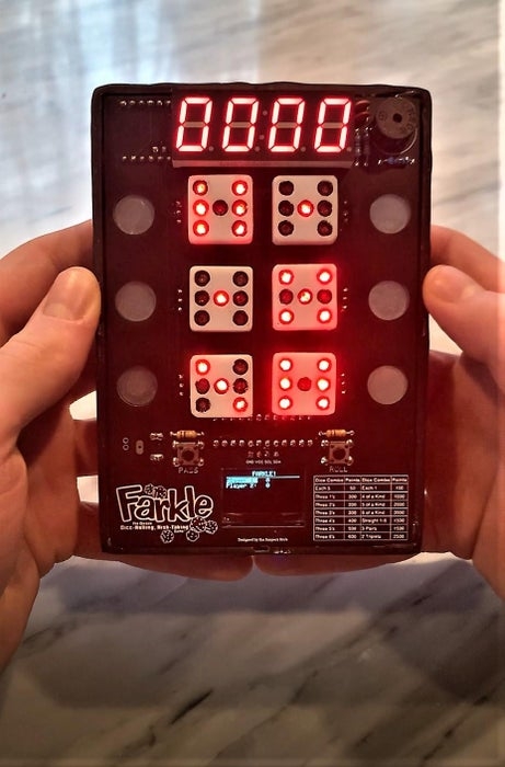
After many hours of schematic drawing, PCB designing, programming the game, and designing the case and die, I created exactly what I had in mind! I was able to finish it just in time for the Holidays, and after testing it with the family, the game worked perfectly! I couldn’t be happier with how it turned out!
Here is a quick rundown of some of the design features of my Farkle game:
– 6 capacitive touch sensors for selecting/de-selecting die
– 2 push buttons to continue round or pass to next player
– 6 electronic LED dice
– 4 digit 7-segment display that displays current score during a players’ round
– 128×64 OLED display that keeps total score of each player during gameplay
– Option for 2-6 players to play the game (working on creating a 1 player game vs. the computer)
– Piezo buzzer that creates sounds during gameplay
– Scoring combinations printed on circuit board for reference
– Portable and powered with a LiPo battery
All in all I had a blast making this game. This was my first experience creating a PCB and the programming was definitely fun and challenging. If you want to make this fun game, follow along!
Supplies
Electronics:
– 2x Ceramic Capacitor (100nF)
– 2x Resistor (30kOhm)
– 2x Resistor (10kOhm)
– Resistor (100 Ohm)
– 2600 mAh Rechargeable Power Bank
– Switch
– Sunyecz22 Farkle PCB Board (Message me and I can send the Gerber files)
Other:
– 3D printer (optional)
– Black and White PLA filament (optional)
– Envirotex Lite Pour On Gloss Finish
– Sandpaper (~80 grit – 1200 grit)
– Clear Acrylic Sheet (12in x 12in square)
Miscellaneous:
– 28 gauge wire
– Wire cutters/strippers
– Soldering iron
– Solder
– Small precision files
– Hot glue
Step 1: Farkle! Rules and Gameplay

Before I begin, it may be helpful to understand how Farkle is played and the rules for the game. There are a few different variations to the game but I stuck with the rules and scoring combinations from this website. This most closely resembles the rules that I remember playing as a kid.
Objective:
To score a minimum of 10,000 points and outscore your opponents
Equipment:
– Six 6-sided dice
– A score sheet and pencil for keeping score
Number of Players:
Traditional Farkle is played with at least two players but is ideally played with 3-8 players.
How to Play:
Note: this is directly from https://www.dicegamedepot.com/farkle-rules/. They explain the rules best in terms of simplicity.
The following Farkle rules are the most commonly used, but there are numerous variations to choose from (I stuck with the basic gameplay for my game, but some of the variations could be easily implemented without additional coding). Before the game begins, players should establish which rules or variations will be used.
One player is chosen to begin and play moves clockwise around the table. Each player in turn rolls all six dice and checks to see if they have rolled any scoring dice or combinations. (See Scoring below.) Any dice that score may be set aside and then the player may choose to roll all the remaining dice. The player must set aside at least one scoring die of their choice if possible but is not required to set aside all scoring dice.
For example, if a player rolled 1-2-2-5-5-6 on their turn, they could set aside the 1 and the two 5’s for scoring, or they could choose to set aside only the 1. Any scoring dice that are not set aside may be rerolled along with the non-scoring dice.
If all six dice have been set aside for scoring (known as having “hot dice”), the player can choose to roll all six dice again and continue adding to their accumulated score or they can bank their points, end their turn, and pass the dice to the next player.
A player’s turn continues until either they decide to stop (at which point they then score their accumulated points) or until they fail to roll any scoring dice on a throw.
If a player scores no points on a roll, this is known as a Farkle. All of their points gained so far on that turn are lost and the dice are passed to the next player.
At the end of a player’s turn, any points they have scored are written down and the dice are passed to the next player.
Scoring:
**Refer to Scoring Guidelines in image above**
Note that scoring combinations only count when made with a single throw. (Example: If a player rolls a 1 and sets it aside and then rolls three 1’s on their next throw, they only score 400 points, not 1000.)
Sometimes a single roll will provide multiple ways to score. For example, a player rolling 1-2-4-5-5-5 could score one of the following:
100 points for the 1
150 points for the 1 and a 5
500 points for the three 5’s
600 points for the 1 and the three 5’s
WINNING:
The first player to score a total of 10,000 or more points wins, provided that no other players with a remaining turn can exceed that score.
Step 2: Schematic and Wiring
So to begin this journey, I started by figuring out what components I wanted to use for this game. I knew that there needed to be a way to select or de-select dice during each round. Rather than utilize only push buttons, I thought it would be cool to use some capacitive touch sensors boards that I had lying around instead. I kept the idea of using two push buttons for the “roll” function and the “pass” function.
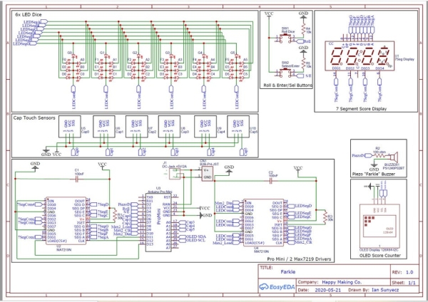
In order to display the current round score and the total score among each player, I chose to use a 4 digit 7 segment display and a 128×64 OLED display respectively. I added a piezo buzzer for sound effects. I also planned to use an Arduino Pro Mini as my microcontroller for the game.
For the 6 die needed for the game, I chose to use standard 3mm through hold LEDs (42 LEDs in total). The issue at this point was how to drive the LEDs and 7 segment display. This awesome website by Eberhard Fahle explains how to utilize MAX7219 IC chips to drive multiple LEDs and even a 7 segment display. I highly recommend checking out that website for more comprehensive information on the hardware and software of these chips. Essentially, the chips implement an SPI interface that only require 3 digital output pins from the Arduino, in addition to Vcc and GND. Each chip can drive up to 64 LED’s and because I am using a total of 42 LED’s for the die (6 die x 7 LEDs per die) and 28 LED’s for the 7 segment (7 LED’s per segment not including the decimal point x 4 segments), I chose to use two separate MAX7219 chips for this. Using two separate chips also made programming the die and 7 segment much easier as I had individual control of both.
After deciding which components I wanted to use, I created a schematic on EasyEDA. By using the datasheet of the 7 segment display as well as Eberhard Fahle’s website, figuring out which pins to connect the LED’s and the display to was pretty straight forward. I also made sure to find my specific components in the EasyEDA library so that pinouts were correct and sizing was appropriate. I have attached the schematic for reference.
Once the schematic was completed, I began wiring the project on my breadboard and running some test code to see if my wiring was correct. While the OLED, 7 segment, dice, and single capacitive touch sensor worked, it was a huge rats nest as you can tell from the pictures. Rather than continue to work from the breadboard prototype, I chose to go right into creating a PCB for it. This would allow me to incorporate all the components and make programming the game much easier.
Step 3: PCB Design and Fabrication
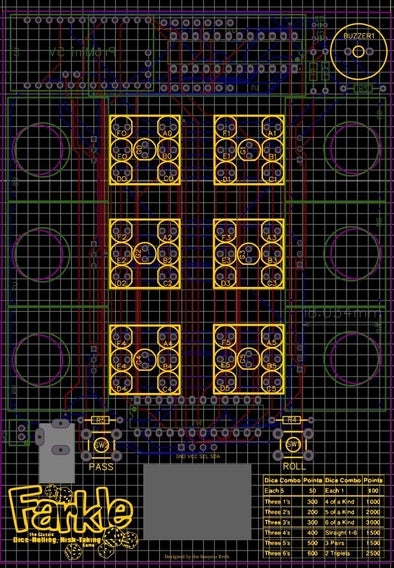
This was my first time designing a PCB and I chose to use EasyEDA as that was my program of choice for the schematic. It was fairly intuitive to use but I certainly used some help getting started. Here is a good video that helped me begin. Once the schematic was completed, I hit “convert to PCB” on the EasyEDA toolbar. From there, it was a matter of arranging the components in a manner that I wanted. This was accomplished by selecting each component, dragging it to where I desired, and selecting which layer I wanted to place it.
I had the idea that the game would be handheld and I figured placing the capacitive touch sensors on the outer edges of the PCB would work best. My idea was to place the touch sensor boards on the bottom of the PCB and create a circular cutout on the board where the touch pad would show through. I then placed each sensors associated dice in between, ensuring that I kept each LED of the die consistent on the board (For example, the first LED for each die (A0, A1, A2, A3, A4, and A5) was placed in the top right corner). I also placed the two push buttons on the front, centered the 7 segment, and created a cutout that would fit the OLED screen. I also added the piezo, resistors, and capacitors to the top layer as I thought it looked cool. Finally, I printed out the Farkle logo and the scoring combination sheet on the top silk layer so players could reference that as needed.
The back of the PCB contained the 2 MAX7219 chips, the Arduino Pro Mini, the touch sensors, and the OLED. I also added pins for a barrel jack and JST connector to power the board. At the point of designing the PCB, I was not exactly sure how I wanted to power the game so I gave myself those two options.
Once happy with the layout, I used the autoroute feature to connect each component per the schematic. I then generated the Gerber files and ordered the PCB’s through JLCPCB! They arrived in a timely manner and I was very happy with how they looked.
If you are interested in the Gerber files just let me know and I would be happy to send them to you!
Step 4: Arduino Program
Creating the code was the most challenging part of this build in my opinion. There were many aspects to it including printing to the 7 segment, illuminating and “rolling” the die, creating images and displaying the score on the OLED, sounding the buzzer, and finally creating the actual game itself. I’ll attach my code below and I tried my best to comment each section. It is open for you to use and critique! I will go through each main component briefly:
7 Segment and Dice:
Again, Eberhard Fahle’s website on using the MAX7219 chips was crucial in writing the code to drive both the 7 segment and the LED dice. First and foremost, he describes how to initialize each chip and I followed those instructions after installing his “LEDControl.h”, the “binary.h”, and the “SPI.h” libraries. He included a sample code on his website on how to print numbers to the 7 segment and I tweaked that for my use. The function is “printNumber()” in my code.
As for the dice, this was a bit more complicated. A simple way to explain how to illuminate each pip of the dice is to think about it in terms of a 7 segment display. I’ve attached an image above but essentially each segment of a 7 segment display can be mapped to that of a 6 sided dice (as a single 6 sided die requires 7 LED’s). Once properly mapped, I was then able to determine which segments needed to be turned HIGH in order to create the numbers 1-6. This provided me with the binary values for each number. From there, I simply used Eberhard’s premade functions from his library to control individual die.
OLED:
I used Adafruit’s GFX and SSD1306 libraries as well as “Wire.h” to help with displaying scores/images on the OLED. The OLED had a couple purposes and I created some functions to do that. Those purposes included:
-Welcome animation on startup
-Screen to instruct players on selecting how many players per game
-Score screen that updates each players score after a players round
-“Farkle” screen displayed when a player Farkles
-Winning animation screen
Piezo Buzzer:
I used Arduino’s tone() and noTone() functions to add sound elements to my game. Specifically, I added sound on the welcome animation startup, when a player Farkles, and on the winning animation. Additionally, I added a short blip sound when a player passes to the next player.
Farkle Gameplay:
The biggest thing in designing the code for the game in my opinion was creating a function to evaluate a players score. For example, lets say a player “rolls” the die at the start of a round and the outcome is {1, 4, 5, 5, 6, 2}. I needed to create a way in which the player could select whatever die he/she wanted, run it through the scoring function, and display the point value on the 7 segment in real time. To do this, a player would touch the associated die’s touch sensor, that individual die would turn OFF, and the number selected would be placed into a new array that was arranged into ascending order. That new array, arranged from low to high, would then be run through my scoring function to evaluate for any points. I created an algorithm above showing this process.
I started by checking the array against the combinations with the most die needed to score. For example, I began by seeing if the array met criteria for a 1-6 straight, then 6 of a kind, then 5 of a kind, then 4 of a kind…., etc. My thinking here was that a player with a full straight, for example {1, 2, 3, 4, 5, 6}, should receive 1500 points for the straight instead of 150 points for the 1 and 5. If the criteria is met to be a straight, then don’t even check points for individual 1’s and 5’s. In short, the program works and is processes fast enough for regular game play pace. I am sure there are more efficient programming methods to accomplish this task and I would love to hear back from you if you have any ideas! If you have any other questions on how/why I did something in the code, I would be happy to answer them as well!
Another tricky part was in coding for a player that wanted to continue his/her round by pressing the “roll” button if they had a die combination that resulted in points. For this, I needed to only animate the “roll” of die that were not selected while keeping the point score on the 7 segment the same. Checking for points for this “new” round is independent of any previous round. If no points were awarded after any roll/pass, a Farkle would occur and that players points for that round were eliminated. The correct scoring adjustments needed to be accounted for on the OLED.
After I finalized the scoring function, the rest of the game was fairly easy to code. It was just making sure the flow of the game was correct from one player to the next. I added a function to check if any player scored over 10,000 points at which point the remaining players had one last chance to outscore their opponent. Finally, I added a winning animation with sound.
Download the code and upload to Arduino:
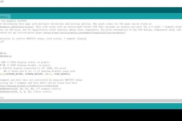
I’ve attached both the “.ino” code as well as the “.c” file. Be sure to download both and place them in the same folder prior to uploading to your Arduino Pro Mini.
Note: I had success with uploading my code to the Arduino Pro Mini using Arduino version 1.8.12. When I tried uploading it using version 1.8.13, I got an “SSD1306 allocation failed” message come across on the serial monitor. This leads me to believe there is some RAM memory issue (despite the program not exceeding the space available) that will not allow the program to run successfully in the newest version. I am currently working on optimizing the program to save space. For now, upload the program using 1.8.12 and you should not run in to any issues.
Source: Farkle! Handheld PCB Game Console