Summary of Fancy LED Hat
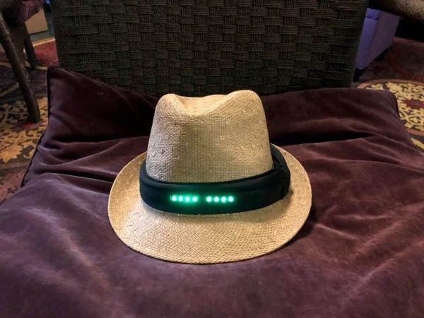
This article details the creation of a motion-sensitive LED hat for a fancy party. The project uses a Teensy LC microcontroller and a Bosch BNO055 sensor to control WS2812 addressable LEDs, reacting to head tilt, gravity, shocks, and spins. The electronics are housed in custom spandex pockets sewn into a standard hat band. The total cost is approximately $80, though experimentation could reduce this.
Parts used in the Fancy LED Hat:
- Teensy LC microcontroller
- Bosch BNO055 based positional sensor
- WS2812 addressable LED strip (1 meter, 144 LEDs/meter)
- Hat with a hatband
- 4.7K ohm resistors
- 3x AAA battery case
- Small gauge solid wire
- Soldering iron and solder
- Matching spandex fabric and thread
I’ve always wanted to do an Arduino project, but never had any great ideas for one until my family was invited to a fancy hat party. With two weeks lead time, I was curious if I could both plan and execute a motion sensitive LED animation hat. Turns out I could! I probably went a little overboard, but the total project cost around $80. With experimentation and some coding you could do it for less.
The goal with the hat was the following:
- Have a set of lights move from the center front of the hat to the back, one light on each side
- Change the speed of the light’s travel dictated by the tilt of the hat front to back
- Allow the lights to reverse when the hat band was tilted downward (i.e. emulate gravity’s effect on the lights)
- Change color based on the tilt of the hat left to right
- Sense shocks, and display a special effect
- Sense the wearer spinning, and display a special effect
- Have it completely contained in the hat
Step 1: Parts Needed
I used the following major components (non-affiliate Amazon links included):
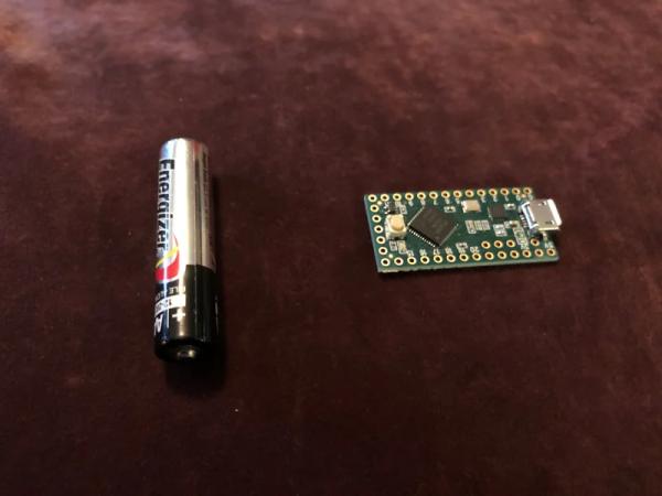
- Teensy LC microcontroller – I chose this over a regular Arduino due to its small size, and it having a special connection for controlling my LEDs, as well as strong library and community support.
- Bosch BNO055 based positional sensor – honestly one of the first I found documentation on. There are much less expensive options, however once you figure out the Bosch it does a lot for you that you would otherwise have to do in code
- WS2812 addressable LED strip – I chose a 1 meter length with 144 LEDs per meter. Having that density helps the light look more like it is moving, rather than individual elements lighting up in sequence.
And the following minor components:
- A hat – any hat with a hatband will do. This is a $6 hat from a local store. If it has a seam in the back it will be easier to get the wiring through. Pay attention to if the hat band is glued on as that will also cause some extra difficulty. This one is sewn along the top, but the bottom pulled up easily.
- 4.7K ohm resistors
- 3x AAA battery case – using 3 AAA batteries outputs voltage exactly in the range the electronics want, which simplifies things. AAA fits into a hat easier than AA and still has great runtime.
- Small gauge wire – I used some solid wire I had laying around from a previous LED project.
- Soldering iron and solder
- Some spandex that matches the inside color of the hat, and thread
Suggested, but optional:
- Quick connectors for the battery wires
- Helping Hands tool, these things are very small and hard to solder
Step 2: Modify the Hat
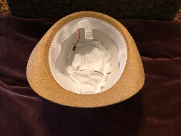
You are going to need a place in the hat to mount the electronics, and a place for the battery. My wife works with clothing professionally, so I asked her for advice and help. We ended up creating two pockets with spandex. The first smaller pocket towards the front is pointed like the hat itself so that when the electronics are installed the positional sensor is held in place fairly well, yet can be easily removed if necessary. The second pocket towards the back is to hold the battery pack in place.
The pockets were sown with thread that matched the color of the hat, all long the crown line. Depending on the style of hat and materials it is made of YMMV with this technique.
We also discovered the hat band tucks into itself on one side, and it was fully sewn to the hat in that location. We had to remove the original seam in order to run the LEDs under the band. During the build it was held in place with pins, and then sewn with matching thread when completed.
Finally we opened the seam on the back of the hat were it is covered by the band. We tucked the wire harness that came with the LEDs through that seam and lined the first LED in the strip to be right on the seam. We then wrapped the LEDs around the hat and cut the strip down so that the last LED would be right next to the first. The LED strip can be held in place just with the hat band, however depending on your band and material you may need to secure the LEDs by sewing or glueing.
Step 3: Wire It Up
The Teensy board and the LEDs will work with anywhere from 3.3v to 5v for power. This is why I chose to use 3 AAA batteries, the output voltage of 4.5v is nicely in that range, and they have plenty of runtime for the way I’ve programmed the LEDs to work. You should be able to get well over 8 hours of runtime.
Wiring the power
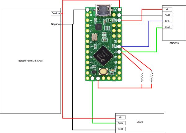
I wired the positive and negative leads from the battery box and LEDs together, then soldered onto the Teensy in appropriate locations. The positive from the battery needs to be connected to the top right pin of the Teensy in the diagram (labelled Vin on the board), and the negative can be wired to any pin labelled GND. Conveniently there is one directly on the opposite side of the board, or right next to the Vin pin. The full pinout diagram for the board can be found on the bottom of this page. And in some cases a paper copy is included when you order the board.
If you are planning on running code that only has a few LEDs turned on at a single time, you can power the LEDs from the Teensy itself, by using a 3.3v output and GND, however if you try to pull too much power you can damage the board. So to give yourself the most options it is best to wire the LEDs to your battery source directly.
Wiring the LEDs
I chose the Teensy LC for this project as it has a pin that makes it much easier to wire up addressable LEDs. On the bottom of the board the pin that is second from the left mirrors Pin #17, but also has 3.3v on it. This is referred to as a pull-up, and on other boards you would have to wire in a resistor to provide that voltage. In the case of the Teensy LC you can just wire from that pin straight to your LEDs data wire.
Wiring the position sensor
Some of the BNO055 boards available are much more strict on voltage and only want 3.3v. Because of this, I wired the Vin on the BNO055 board from the dedicated 3.3v output on the Teensy, which is the 3rd pin down on the right. You can then connect the GND on the BNO055 to any GND on the Teensy.
The BNO055 position sensor uses I2c to talk to the Teensy. I2c requires pull-ups, so I wired two 4.7K ohm resistors from a 3.3v output on the Teensy to pins 18 and 19. I then wired pin 19 to the SCL pin on the BNO055 board, and 18 to the SDA pin.
Wiring tips/tricks
To do this project I used solid wire rather than stranded. One advantage to solid wire is while soldering to prototype boards like these. You can strip some wire, bend it to 90 degrees, and insert it through the bottom of one of the terminals, so that the cut end of the wire is sticking up above your board. You then only need a small amount of solder to hold it to the terminal, and you can cut off the excess easily.
The solid wire can be more difficult to work with as tends to want to stay how it is bent. However for this project that was an advantage. I cut and shaped my wires in such a way that the orientation of the positional sensor would be consistent as I inserted and removed the electronics from the hat for tweaking and programming.
Step 4: Programming
Now that everything is assembled you will need an Arduino compatible programming tool. I used the actual Arduino IDE (works with Linux, Mac, and PC). You will also need the Teensyduino software to interface with the Teensy board. This project heavily uses the FastLED library to do the color and position programming of the LEDs.
Calibrating
The first thing you will want to do is go to Kris Winer’s excellent GitHub repository for the BNO055 and download his BNO_055_Nano_Basic_AHRS_t3.ino sketch. Install that code with the Serial Monitor running and it’ll tell you if the BNO055 board properly comes online and passes its self tests. It will also walk you through calibrating the BNO055, which will give you more consistent results later.
Getting started with the Fancy LED sketch
The code for the Fancy LED hat specifically is attached, and also on my GitHub repository. I plan on making more tweaks to the code and those will be posted on the GitHub repo. The file here reflects the code when this Instructable was published. After downloading and opening the sketch, there are a few things you will need to change. Most of the important values to change are in the very top as #define statements:
- Line 24: #define NUM_LEDS 89 – change this to the actual number of LEDs on your LED strip
- Line 28: #define SERIAL_DEBUG false – you will probably want to make this true, so that you can see output on the serial monitor
Position detection code
Position detection and most of your tweaking starts at line 742, and goes through 802. We get Pitch, Roll, and Yaw data from the position sensor and use it to set values. Depending on how your electronics are mounted you may need to change these. If you mount the position sensor with the chip towards the top of the hat, and the arrow next to X printed on the board pointed towards the front of the hat you should see the following:
- Pitch is nodding your head
- Roll is tilting your head, e.g. touch your ear to your shoulder
- Yaw is which direction. you are facing (North, West, etc).
If your board is mounted in a different orientation you will need to swap Pitch/Roll/Yaw for them to behave how you would like.
To adjust the Roll settings you can change the following #define values:
- ROLLOFFSET: with your hat stable and as centered as it can be, if the Roll isn’t 0, change this by the difference. I.e. if you are seeing Roll at -20 when your hat is centered, make this 20.
- ROLLMAX: the maximum value to use for Roll measurement. Easiest to find by wearing the hat and moving your right ear towards your right shoulder. You’ll need a long USB cable to do this while using the serial monitor.
- ROLLMIN: the lowest value to use for Roll measurement, for when your tilting your head left
Similarly, for Pitch:
- MAXPITCH – the maximum value when you are looking up
- MINPITCH – the minimum value when you are looking down
- PITCHCENTER – the pitch value when you are looking straight forward
If you set SERIALDEBUG to true at the top of the file you should see the current values for Roll/Pitch/Yaw output to the serial monitor to help tweak these values.
Other parameters you may want to change
- MAX_LED_DELAY 35 – the slowest that the LED particle can move. This is in milliseconds. It is the delay from moving from one LED to the next in the string.
- MIN_LED_DELAY 10 – the fasted that the LED particle can move. As above it is in milliseconds.
Conclusion
If you have gone this far, you should have a fully functioning, and fun, LED hat! If you want to do more with it, the next page has some advanced information on changing settings, and doing your own things. as well as some explanation of what the rest of my code is doing.
Step 5: Advanced and Optional: Inside the Code
Impact & spin detection
Impact/spin detection is done using the high-G sensor functions of the BNO055. You can tweak the sensitivity of it with the following lines in initBNO055():
- Line #316: BNO055_ACC_HG_DURATION – how long the event has to last
- Line #317: BNO055_ACC_HG_THRESH – how hard the impact needs to be
- Line #319: BNO055_GYR_HR_Z_SET – rotation speed threshold
- Line #320: BNO055_GYR_DUR_Z – how long the rotation even has to last
Both values are 8 bit binary, currently the impact is set to B11000000, which is 192 out of 255.
When an impact or spin is detected the BNO055 sets a value which the code looks for right at the beginning of the Loop:
// Detect any interrupts triggered, i.e. due to high G
    byte intStatus = readByte(BNO055_ADDRESS, BNO055_INT_STATUS);
    if(intStatus > 8) {
      impact();
    } else if(intStatus > 0) {
      spin();
    }
Look for the void impact() line above in the code to change the behavior on impact, or void spin() to change the spin behavior.
Helpers
I’ve created a simple helper function (void setAllLeds()) for quickly setting all the LEDs to a single color. One use it to turn them all off:
setAllLeds(CRGB::Black);
Or you can pick any color recognized by the FastLED library:
setAllLeds(CRGB::Red);
There is also a fadeAllLeds() function that will dim all the LEDs by 25%.
The Particle class
In order to greatly simplify wiring I wanted to use a single string of LEDs, but have them behave like multiple strings. Since this was my first try I wanted to keep it as simple as possible, so I treat the one string as two, with the middle LED(s) being there the split would be. Since we could either have an even number or an odd number, we need to account for that. I start with some global variables:
/*
 * Variable and containers for LEDs
 */
CRGB leds[NUM_LEDS];

static unsigned int curLedDelay = MAX_LED_DELAY;
static int centerLed = NUM_LEDS / 2;
static int maxLedPos = NUM_LEDS / 2;
static bool oddLeds = 0;
static bool particleDir = 1;
static bool speedDir = 1;

unsigned long dirCount;
unsigned long hueCount;
And some code in setup():
if(NUM_LEDS % 2 == 1) {
     oddLeds = 1;
     maxLedPos = NUM_LEDS/2;
  } else {
     oddLeds = 0;
     maxLedPos = NUM_LEDS/2 - 1;
  }
If we have odd numbers, we want to use the 1/2 point as the middle, otherwise we want the 1/2 point – 1. This is easy to see with 10 or 11 LEDs:
- 11 LEDs: 11/2 with integers should evaluate to 5. and computers count from 0. So 0 – 4 is one half, 6 – 10 is the other half, and 5 is between them. We treat #5 in this case as if it was part of both, i.e. it is #1 for both virtual strings of LEDs
- 10 LEDs: 10/2 is 5. But since computers count from 0 we need to remove one. Then we have 0 – 4 for one half, and 5 – 9 for the other. #1 for the first virtual string will be 4, and #1 for the second virtual string will be #5.
Then in our particle code we have to do some counting from our overall position to the actual positions on the LED string:
if(oddLeds) {
        Pos1 = centerLed + currPos;
        Pos2 = centerLed - currPos;
      } else {
        Pos1 = centerLed + currPos;
        Pos2 = (centerLed -1) - currPos;
      }
The code also has conditions where the particle can change directions, so we also have to take that into account:
if(particleDir) {
        if((currPos == NUM_LEDS/2) && oddLeds){
          currPos = 0;
        } else if((currPos == NUM_LEDS/2 - 1) && (!oddLeds)){
          currPos = 0;
        } else {
          currPos++;
        }
      } else {
        if((currPos == 0) && oddLeds){
          currPos = centerLed;
        } else if((currPos == 0) && (!oddLeds)){
          currPos = centerLed - 1;
        } else {
          currPos--;
        }
      }
So we use the intended direction (particleDir), to calculate which LED should be lit next, but we also have to consider if we have reached either the real end of the LED string, or our center point, which also acts as an end for each of the virtual strings.
Once we’ve figured all that out, we light up the next light as necessary:
if(particleDir) {
        if(oddLeds) {
          Pos1 = centerLed + currPos;
          Pos2 = centerLed - currPos;
        } else {
          Pos1 = centerLed + currPos;
          Pos2 = (centerLed -1) - currPos;
        }
      } else {
        if(oddLeds) {
          Pos1 = centerLed - currPos;
          Pos2 = centerLed + currPos;
        } else {
          Pos1 = centerLed - currPos;
          Pos2 = (centerLed -1) + currPos;
        }
      }
      leds[Pos1] = CHSV(currHue, 255,255);
      leds[Pos2] = CHSV(currHue, 255,255);

      FastLED.show();<br>}
Why make this a class at all? As it is, this is pretty straightforward and doesn’t really need to be in a class. However I have future plans to update the code to allow for more than one particle to occur at a time, and have some working in reverse while others are going forward. I think there are some really great possibilities for spin detection using multiple particles.
Source: Fancy LED Hat
- Why was the Teensy LC chosen over a regular Arduino?
The Teensy LC was selected for its small size, strong library support, and a special pin connection that simplifies controlling LEDs. - How many batteries are needed and why?
Three AAA batteries are used because they provide exactly 4.5v, which fits the 3.3v to 5v range required by the electronics. - What is the recommended runtime for the battery setup?
The author states you should be able to get well over 8 hours of runtime with the three AAA batteries. - How do I calibrate the position sensor?
You must download Kris Winer's BNO_055_Nano_Basic_AHRS_t3.ino sketch from his GitHub repository and run it with the Serial Monitor. - Which library is heavily used for color and position programming?
The FastLED library is used extensively for the color and position programming of the LEDs. - How does the code handle odd versus even numbers of LEDs?
The code checks if NUM_LEDS is odd or even to determine the center point and how to split the string into two virtual strings. - Can I change the speed of the light travel?
Yes, the speed is dictated by the tilt of the hat front to back and can be adjusted via MAX_LED_DELAY and MIN_LED_DELAY values. - How are impacts and spins detected in the code?
Impact and spin detection use the high-G sensor functions of the BNO055, checking specific interrupt status values in the loop. - Where should the LED strip be positioned on the hat?
The first LED should be lined up right on the opened seam at the back of the hat where the wire harness enters.