What is physical computing?
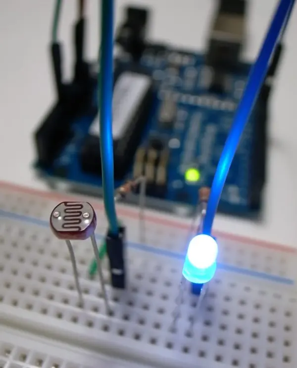
Physical computing involves constructing physical interfaces that interact with the analog world. This entails assembling circuits using microcontrollers, wires, sensors, LEDs, motors, and similar components, which are then controlled by customized software. For example, one might program the software to activate an LED when a photocell sensor detects a light level below 100. Beyond its educational benefits in reinforcing programming concepts, physical computing extends into diverse applications such as art, support systems for ALS patients, immersive installations, experimental music, fashion, and water quality testing.
While there are parallels between robotics and physical computing, the latter primarily focuses on developing interfaces that explore the human body’s interaction with the digital realm, rather than creating autonomous robots independent of human or environmental inputs.
Using a Microcontroller
What’s a Microcontroller?
A microcontroller is a compact computer capable of receiving input from sources like sensors and switches, and controlling outputs such as lights, motors, and other devices. They find broad application in DIY projects, robotics, artistic installations, industrial settings, and the Internet of Things.
When working with a microcontroller platform, such as Arduino in our case, there are two key components: hardware and software. The hardware comprises the microcontroller itself, its input/output pins, and any peripherals attached to it. Software refers to the programs you develop to manage the microcontroller and its connected devices.
Arduino, the microcontroller platform we will use in this class, was originally created by educators to assist design students—many of whom lacked engineering backgrounds—in crafting physical interfaces.
The Arduino provides a free integrated development environment (IDE), available for download from the Arduino website (download it here). This software suite enables you to write code and upload it directly to the Arduino board.
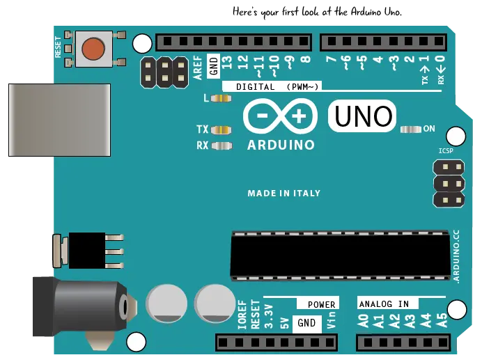
Arduino Uno
While there are numerous versions of Arduino available, we will specifically utilize the Arduino Uno for this purpose.
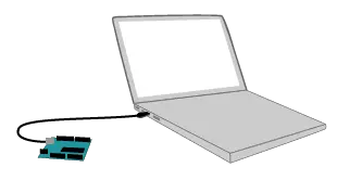
To program the Arduino, first download and install the Arduino IDE (detailed instructions can be found here). The laptops in our Maker Space already have this software pre-installed. Next, connect the Arduino to your computer using a USB A-B cable. If you’re using a newer Macintosh laptop, you’ll need a USB-C to USB adapter.
Parts of an Arduino Uno
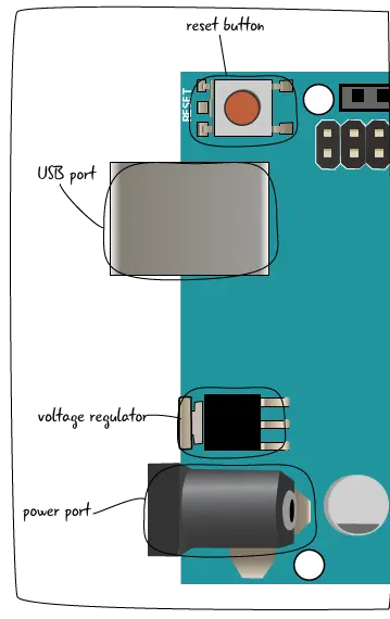
Let’s take a closer look at the components of the Arduino. First, we’ll examine the left side.
Reset Button: This button resets the currently uploaded code on your Arduino. Its location may vary on different boards, but it is the only button present.
USB Port: This port accepts a standard A-to-B USB cable, commonly used with printers and other computer peripherals. The USB port serves two primary functions: it allows for programming the board by connecting it to a computer, and it can also supply power to the Arduino if the power port (described below) is not used.
Voltage Regulator: The voltage regulator converts the input power from the power port (described below) into the standard 5 volts and 1 amp used by the Arduino. Note that this component can become very hot and should be handled with care.
Power Port: This port features a barrel-style connector that accommodates power input from either a wall adapter or a battery. When using this port, the Arduino operates independently of the USB cable. The Arduino can safely handle input voltages ranging from 5V to 20V, but connecting higher voltages can cause damage.
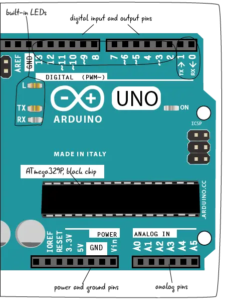
Now, let’s proceed to examine the remainder of the board.
Built-in LEDs: These LEDs indicate the presence of power and activity, showing whether your Arduino is transmitting or receiving data.
Digital I/O pins: The holes on this side of the board are known as digital input/output (I/O) pins. They serve dual purposes: sensing signals from the external environment (input) or controlling lights, sounds, or motors (output).
TX/RX pins: Pin 0 and Pin 1 are designated as TX and RX pins. These are crucial for transmitting and receiving data between the Arduino and a connected computer. It’s important to avoid leaving these pins unused.
ATmega328P, black chip: Positioned at the center of the board, the black ATmega328P chip serves as the Arduino’s central processing unit (CPU). It processes both the inputs and outputs, as well as executing the programming code uploaded to the Arduino.
Power and ground pins: These pins are dedicated to power distribution. They allow you to supply power from your Arduino to your breadboard circuit.
Analog pins: These pins are capable of reading sensor values across a spectrum of analog voltages, rather than simply detecting digital on/off states.
Settings in the software
Now that we’ve familiarized ourselves with the components of the Arduino and understood that programming is done through Arduino software, we need to configure a few settings in the software before starting. This ensures that the Arduino can communicate properly with your computer.
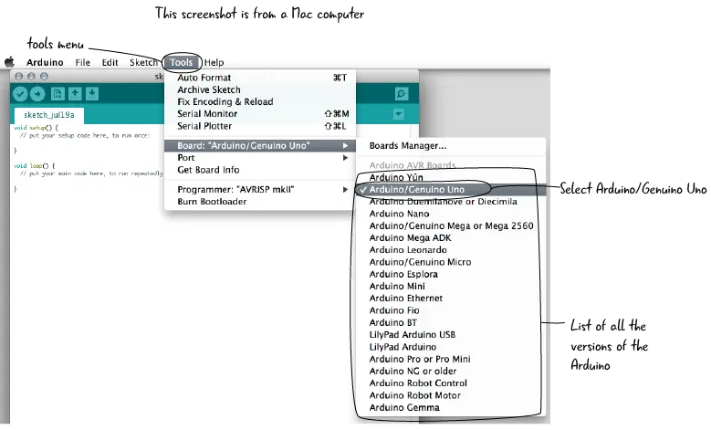
Launch the Arduino software. Once opened, navigate to the Tools menu, then select Board. From the drop-down menu that appears, choose Arduino Uno/Genuino.
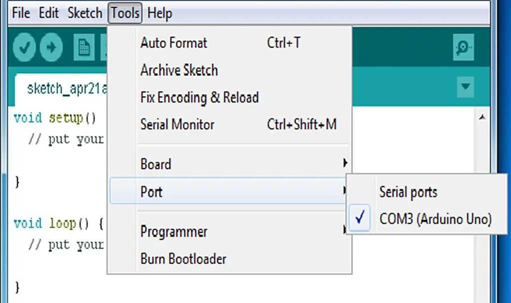
You also need to designate a Serial Port for your Arduino to establish communication with the computer. A port serves as the communication channel linking your Arduino to the computer. On a Windows computer, navigate to the Tools menu, then select Port, followed by choosing the appropriate COM port indicated. It should resemble the screenshot provided below.
Programming the Arduino
As mentioned earlier, the Arduino IDE is available for free download from their website. Detailed instructions on how to install and configure the IDE can be found here.
What’s an IDE?
An IDE, which stands for integrated development environment, is a software application designed for writing and testing code in the programming language supported by the IDE.
If you have programming experience, you may have used another IDE to write, test, debug, and compile your code into executable programs. If you’re new to programming, the Arduino IDE is an excellent starting point because it is straightforward and user-friendly.
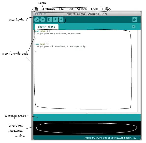
The Arduino team has developed an IDE specifically tailored for their devices, equipped with essential features. It includes a built-in code editor for creating and editing code files. Within the IDE, you can test your code and address issues using a message area that highlights errors and a console providing detailed error messages. Additionally, the IDE offers buttons for verifying your code, saving it, opening new code windows, uploading code to your Arduino, and more.
The sketch
In the Arduino IDE, your program is referred to as a sketch, which serves as the fundamental unit of Arduino programming. The IDE provides example sketches that demonstrate various functionalities achievable with Arduino.
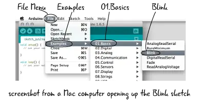
To begin, connect your computer to the Arduino using a USB A-B cable. Launch the Arduino IDE and navigate to File > Examples > 01.Basics > Blink. This action will open the Blink sketch, allowing you to explore, save, and upload it as needed.
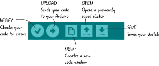
Let’s examine the buttons located at the top of the IDE, specifically within the sketch window. The Verify button checks your code for errors, the Upload button sends your code to the Arduino, the New button creates a new code window, the Open button allows you to open a previously saved sketch, and the Save button saves your current sketch.
Here’s an annotated screenshot of the Blink sketch, highlighting its three main sections.
Comments serve as notes intended for anyone reading your code, including yourself when revisiting a sketch or others with whom you share your code. Comments do not affect how the computer interprets the code and are solely for providing context or explanations of your intentions or the program’s overall functionality.
The setup() function is where you initialize initial conditions for your code. It runs only once, either when you start the program or power up your Arduino.
The loop() function is where you place code that you want to execute repeatedly. This section typically contains all the code responsible for creating the desired functionality. For instance, in the Blink sketch, you’ll find the code that toggles the LED on and off within this function.
Save and rename the sketch!
Once you’ve reviewed the Blink Sketch, save it with a new name. Navigate to File > Save As > MyBlink, for instance. This prevents overwriting the original example files and allows you to modify the example code to better grasp its functionality. Remember, saving your work frequently is a good habit to adopt.
Verify and Upload
Let’s confirm the sketch by verifying it and then uploading it to the Arduino. Click the Verify button to check your code. Even with example sketches, it’s beneficial to develop the habit of verifying your code. The bottom of the window will display messages providing insights into your sketch, including any issues if they arise.
Once verified, you can proceed to upload your code. Ensure your Arduino is connected to the computer and configured correctly. Then, click the Upload button. You should observe the LED near pin 13 on the Arduino beginning to blink on and off.
Follow this link for complete project: Exploring the Fusion of Physical Computing and Creative Expression

