
Summary of Random Sensor Project KY-027 Magic Light Cup Module
The article describes a game project using two KY-027 Magic Light Cup modules, LEDs, and a passive buzzer controlled by an Arduino UNO. Tilting the modules changes a shared brightness value via their mercury tilt switches; PWM drives LEDs to simulate light transferring between cups. The goal is to stop the buzzer by bringing brightness into a target range (example 125–130). Serial Monitor output can show brightness for debugging. Wiring and example Arduino code are provided.
Parts used in the KY-027 Magic Light Cup Game:
- Arduino UNO
- Breadboard
- Jumper wires
- KY-027 Magic Light Cup Module (pair)
- Passive buzzer
Sensor Description
The KY-027 Magic Light Cup module consists of two boards, each equipped with an LED and a mercury tilt switch. By utilizing PWM to control the LEDs on both modules, you can simulate the visual effect of light “magically” transferring between them when they are tilted, reminiscent of pouring water between cups, which inspired its name.
Alternatively, this pair can function as a tilt sensor. I am considering creating an enjoyable game with it. The objective would be to tilt the board until the LED brightness reaches a level between two predefined values, or for a more challenging game, precisely matches a single number (adjustable via code) to stop a buzzer.
If determining the LED brightness directly from the Light Cup Module proves too challenging during gameplay, brightness readings will be available on the Serial Monitor.
Requirements
- Arduino UNO
- Breadboard Jumper Wire
- KY-027 Magic Light Cup Module
- Passive Buzzer
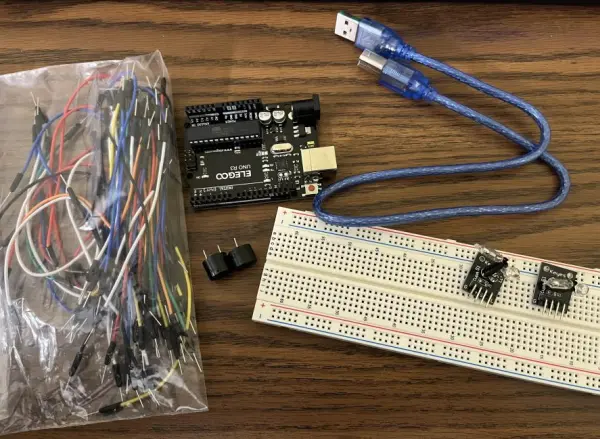
- Step 1: Plugin the Magic Light Cup Module pair
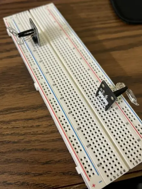
- Step 2: Connect GND Pin with GND rail & VCC Pin of Light Cup Module with 5V rail of Breadboard
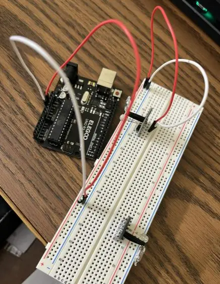
- Step 3: Connect Signal Pin with Digital Pin-7 of Arduino Uno
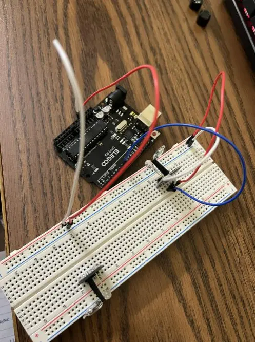
- Step 4: Connect LED Pin of Light Cup Module with Digital Pin-5 of Arduino Uno
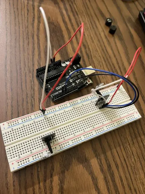
- Step 5: Repeat step 2 on the breadboard for the 2nd Light Cup Module
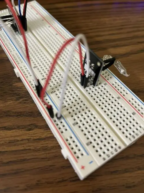
- Step 6: Connect Signal Pin with Digital Pin-4 of Arduino Uno
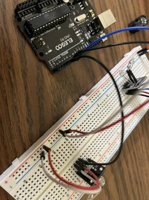
- Step 7: Connect LED Pin of Light Cup Module with Digital Pin-6 of Arduino Uno
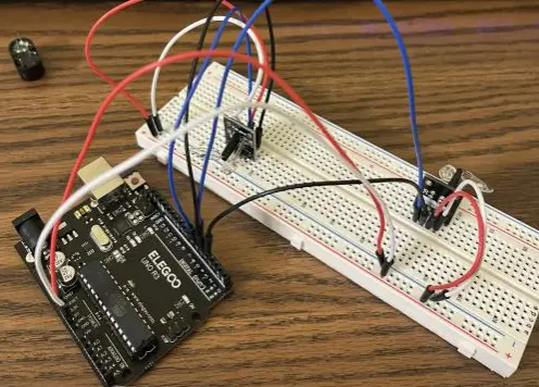
Code: test with what we have so far
int ledPinA = 5;

int switchPinA = 7;

int switchStateA = 0;

int ledPinB = 6;

int switchPinB = 4;

int switchStateB = 0;

int brightness   = 0;

void setup()

{

  pinMode(ledPinA, OUTPUT);

  pinMode(ledPinB, OUTPUT);

  pinMode(switchPinA, INPUT);

  pinMode(switchPinB, INPUT);

}

void loop()

{

  switchStateA = digitalRead(switchPinA);

  if (switchStateA == HIGH && brightness != 255)

  {

   brightness ++;

  }

  switchStateB = digitalRead(switchPinB);

  if (switchStateB == HIGH && brightness != 0)

  {

   brightness –;

  }

  analogWrite(ledPinA, brightness);  //  A slow fade out

  analogWrite(ledPinB, 255 – brightness);  // B slow bright up

  delay(20);

}
Step 8: Plug the passive buzzers in, connect the Buzzer (+) to Arduino Pin 2 and the Buzzer (-) to Arduino Pin GND
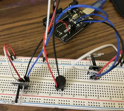
Step 9: When the brightness is not between 125 and 130, buzz
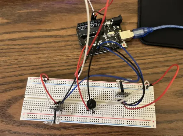
Code
int ledPinA = 5;

int switchPinA = 7;

int switchStateA = 0;

int ledPinB = 6;

int switchPinB = 4;

int switchStateB = 0;

int brightness   = 0;

int buzzerPin = 2;

void setup()

{

  Serial.begin (9600);

  pinMode(ledPinA, OUTPUT);

  pinMode(ledPinB, OUTPUT);

  pinMode(switchPinA, INPUT);

  pinMode(switchPinB, INPUT);

  pinMode(buzzerPin, OUTPUT);

}

void loop()

{

  if (brightness <= 125 || brightness >= 130) {

    tone(buzzerPin, 100);

  }

  else {

    noTone(buzzerPin);

  }

  switchStateA = digitalRead(switchPinA);

  if (switchStateA == HIGH && brightness != 255)

  {

   brightness ++;

  }

  switchStateB = digitalRead(switchPinB);

  if (switchStateB == HIGH && brightness != 0)

  {

   brightness –;

  }

  Serial.println(brightness);

  analogWrite(ledPinA, brightness);  //  A slow fade out

  analogWrite(ledPinB, 255 – brightness);  // B slow bright up

  delay(20);

}
Follow this link for complete project: Random Sensor Project KY-027 Magic Light Cup Module
- What is the objective of the game?
The objective is to tilt the boards until the LED brightness reaches a target range (example 125–130) to stop the buzzer. - How do the KY-027 modules affect brightness?
Each KY-027 module has a mercury tilt switch; tilting one module increments brightness and tilting the other decrements brightness in code. - Which Arduino pins are used for the LED outputs?
The example uses digital pins 5 and 6 for LED PWM outputs. - Which pins read the tilt switches?
The example uses digital pins 7 and 4 for the signal pins of the two KY-027 modules. - How is the buzzer controlled in the project?
The passive buzzer is connected to Arduino pin 2 and tone/noTone is used; it buzzes when brightness is outside the target range. - Can brightness be monitored during gameplay?
Yes, the code prints brightness values to the Serial Monitor for debugging and monitoring. - What power connections are required for the modules?
Connect each KY-027 module VCC to 5V and GND to the Arduino GND rail on the breadboard. - What is the PWM behavior for the two LEDs?
analogWrite(ledPinA, brightness) sets LED A; LED B is set to 255 minus brightness to create opposite fading effects.
