Resources
Adafruit ARDX – v1.3 Experimentation Kit for Arduino
Experimenters Guide for Arduino (PDF)
Bread Board Layouts (PDF)
Arduino Tutorial Bundle (Instructable)
This Arduino Tutorial is going to be very similar to the Arduino Tutorial Bundle Instructable but because we are working on this in our class I figured Instructables would be a good place to organize our YouTube videos and add some more help. To sum up the difference between the two tutorials, Arduino Tutorial Bundle is the basically the book that is linked in the references an includes pictures steps and the code. This instructable has the steps I used to when following the Experimenters Guide, and my classmates YouTube videos.
—————————————————–
General Information:
My first problem was that Windows 8 did not install the driver for the arduino. Windows 8 gave me an error message saying that the driver was unsigned. To get round the new windows 8 security checks I followed THIS guide. Basically use Advanced Startup to start with Disable Driver signature Enforcement. our your windows 7 PC
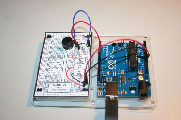
I used a Pin to Poke a hole through the paper where the wires should go so that the holes in the bread board are easier to find and its nicer on the parts.
The second half of the kit and some of the less complicated ones don’t have any components on the left side of the board.I aligned the grid paper to the right side of the bread board with only the right pins to hold it.
To store the extra pieces from the kit and to keep the resistors organized i placed everything on a spare bread board.
the .gif pictures don’t align up exact. this is my attempt at making 3d stereoscopic gif pictures.
Step 1: CIRC-01 Blinking LED
Assembly is fairly straight forward, if you use the bread board templates the holes line up close enough. The little boxes that say [ to …. ] get plugged in the arduino somewhere. for example [ to pin 13 ] is plugged into pin 13.
The code says the led is on pin 13 then it runs a loop where it sets the led to be on then off.
Basic instructions are at ”’CIRC-01”’ – Getting Started – (Blinking LED)
Instead of writing all the code from scratch you can copy the code from the PDF or http://ardx.org/CODE01.
3 upload the program
file> upload should do the trick if, not go to tools> serial port and try a different channel.
YouTube Videos
Step 2: CIRC-02 8 LED Fun
On the LEDs remember that the longer leg is positive. The legs on the resistors bend very easily so it might help to to use a pencil to poke a hole in the paper then sticking in the resistors. This uses up most of the digital pins out.
The code is much longer then the first lab. It starts by designating the pins. then it states the different loops, one loop starts each light one at a time and the other has a loop inside it , they both do the same thing but with a loop there is much less code.
Basic instructions are at ”’CIRC-02”’ – Multiple LEDs – (8 LED Fun)
copy the code from http://ardx.org/CODE02
Step 3: CIRC-03 Spin Motor Spin
On my circuit i did not need the optional capacitor.
I attached a piece of blue tape to the motor so that I could see that it spun.
The legs of the transistor are not labeled but if you are using the breadboard layout just place it in the same direction as its drawn.
The codes say to use pin 9 then goes to say if pin 9 is + or – 5 volts. Below it uses speed and time variables to control the motor.
Basic instructions are at ”’CIRC-03”’ – Spin Motor Spin – (Transistor & Motor)
copy the code from http://ardx.org/CODE03
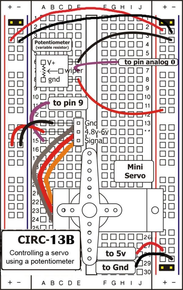
Step 4: CIRC-04 A Single Servo
This project might be easier then the first. Most the electronics for the servo motor are inside it and it is very quick to plug into the bread board. When the motor is running it does make a funny clicking sound but that is from the code.
The code says to rotate 1 degree then wait 15 milliseconds before turning again.
Basic instructions are at ”’CIRC-04”’ – A Single Servo – (Servos)
copy the code from http://ardx.org/CODE04
Step 5: CIRC-05 8 more LEDs
This is the hardest circuit to assemble so far, if you wanted to make an LED cube it would probably be in this method of controlling the LEDs.
The Arduino and the shit registers work together. The shift register act as extra pins on the arduino and do what the arduino tells it to. the shift register uses the serial communication link to talk with the arduino.
Basic instructions are at ”’CIRC-05”’ – 8 More LEDs – (74HC595 Shift Register)
copy the code from http://ardx.org/CODE05
For more detail: Experimenters Guide for Arduino as Performed at OIT