Summary of Infinity Mirror Clock using Arduino
This article details the construction of a Smart Infinity Mirror Clock using an Arduino. The device functions as a clock with programmable Bluetooth colors, features an IR sensor to turn off LEDs when someone approaches for normal mirror use, and includes a touch button to toggle between clock and rainbow modes. It also supports automatic night mode and displays a rainbow effect every 15 minutes.
Parts used in the Smart Infinity Mirror Clock:
- Standalone Arduino or Arduino mini pro
- RTC Module – DS1302
- LM2596 Step Down Adjustable Power Supply Module
- 1m 60LEDs/M Addressable RGB LED Strip (WS2812B)
- HC-05 Bluetooth module
- IR Proximity Sensor components (4 IR LEDs and 1 IR LED detector)
- Touch Pad
- 9V – 2A Adapter
- CP2102 USB-to-TTL converter
- 2 pieces of 8mm plywood (600mm x 600mm)
- 1 piece of 18mm block-board (600mm x 600mm)
- 1 circular 6mm mirror (400mm dia)
- 1 circular 6mm glass (400mm dia) with silver sun-control film
- 1 small round steel plate (100mm dia)
- N45 Silicon adhesive
- Black Paint
- Black Vinyl
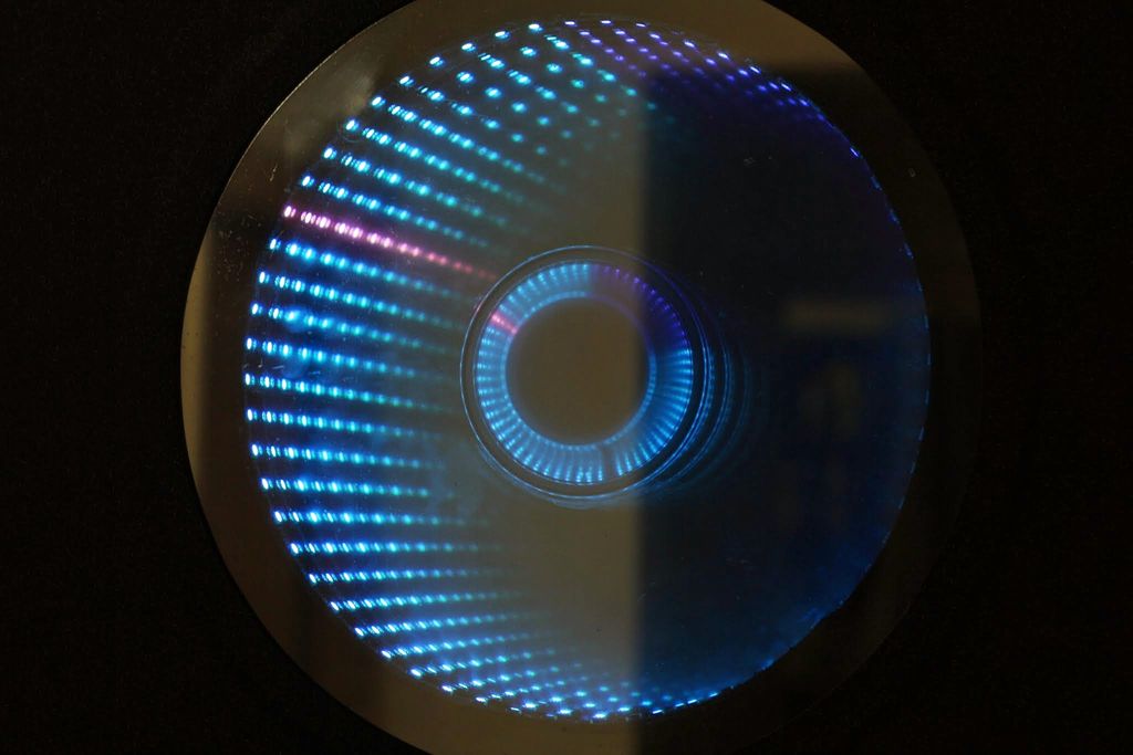
Ever since my addressable RGB LED strips (WS2812B) came from Aliexpress, I’ve been fascinated with LED projects. Following up on my success with my Charlieplexed LED clock, I wanted to create something with more Jazz..
While browsing google images, I came across an instructable for an Arduino Infinity Mirror and the brain cells started working in overdrive. Why shouldn’t I make an infinity mirror, that’s also a clock !!
Features:
- Works like a clock – the colours of the hands are user-programmable over bluetooth
- Has an IR sensor to sense if someone is coming near the mirror. Switches off the LEDs, so that this can be used as a normal mirror 🙂
- Shows a rainbow effect every 15 minutes (time is user adjustable)
- Has a touch button to toggle between clock and rainbow effects
- Switches to night mode between midnight and 7:00 AM – can be changed in the code.
- Can be programmed over bluetooth – so you do not need to take it off the wall if you need to update the code
Step 1: Electronics
- A Standalone Arduino: http://dushyant.ahuja.ws/2013/10/standalone-arduin… OR Arduino mini pro: http://www.aliexpress.com/item/10Pcs-Lot-Pro-Mini-…
- RTC Module – DS1302: http://fabtolab.com/DS1302-RTC-module?search=rtc
- LM2596 Step Down Adjustable Power Supply Module 1.3V-35V: http://cgi.ebay.in/ws/eBayISAPI.dll?ViewItem&item=…
- 1m 60LEDs/M Addressable RGB LED Strip (WS2812B): http://www.aliexpress.com/item/1M-WS2812-WS2812B-6…
- HC-05 Bluetooth module: http://www.aliexpress.com/item/RS232-TTL-LC-05-Wir…
- IR Proximity Sensor: http://www.instructables.com/id/Simple-IR-proximit…4 IR LEDs; 1 IR LED detector: http://www.evelta.com/industrial-control/sensors/5…
- Touch Pad: http://www.aliexpress.com/item/Touch-Pad-Brick-Sen…
- 9V – 2A Adapter
- CP2102 USB-to-TTL (the RST pin on the CP2102 is not for resetting the arduino – you have to solder a wire to the DTR pad on the PCB – which sends a reset signal to program the arduino. This has to be connected to the DTR pin on the Arduino
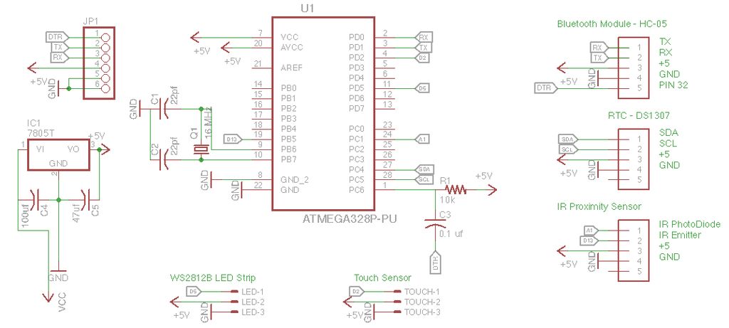
Step 2: The Circuit
The circuit is very simple:
- LED Strip – Connect power to the LM2596 Step Down Adjustable Power Supply Module – ensure you adjust the pot so that the output is 5V; Connect the ground to the common ground; Connect data to pin D5 of the Arduino
- Touch Sensor – data to pin D2 of Arduino
- RTC Module – SDA and SCL to the A4 and A5 of the Arduino respectively
- Bluetooth Module – Connect RX to Arduino’s TX and TX to Arduino’s RX. You will have to break-out pin 32 on the module to the DTR pin on the Arduino (This allows you to program the Arduino over bluetooth)
- IR Proximity Sensor – create the sensor as per this instructable: http://www.instructables.com/id/Simple-IR-proximit… – connect the photo-diode to A1 (A0 on the instructable schematic) and the IR LEDs to D13 (D2 on the instructable schematic)
- Connect the Power 9V 2A Power supply to the input of the 7805 and the LM2596
To setup the bluetooth programming circuit, please follow this link: http://makezine.com/projects/diy-arduino-bluetooth…
 Infinity Mirror.sch372 KB
Step 3: The Code
This clock uses the following libraries (and all thanks to the authors of these libraries):
- RTCLib Arduino Library: https://github.com/adafruit/RTClib
- FastLED Arduino Library v2.1: http://fastled.io/ https://github.com/FastLED/FastLED/tree/FastLED2.1
- SerialCommand Arduino Library: https://github.com/scogswell/ArduinoSerialCommand…
- TimerOne Arduino Library: https://github.com/scogswell/ArduinoSerialCommand…
The latest version of the code can be downloaded from the project github: https://github.com/dushyantahuja/Smart-Infinity-Mi…
#include <Wire.h>
#include "RTClib.h"
#include "FastLED.h"
#include <SoftwareSerial.h>
#include <SerialCommand.h>
#include "EEPROM.h"
#include "TimerOne.h"

#define NUM_LEDS 60
#define DATA_PIN 5
#define UPDATES_PER_SECOND 100
#define SWITCHPIN 2

// Variables for IR Proximity

int IRpin = A1;               // IR photodiode on analog pin A1
int IRemitter = 13;            // IR emitter LED on digital pin 4

//

CRGBPalette16 currentPalette;
TBlendType    currentBlending;

CRGB leds[NUM_LEDS],minutes,hours,seconds,l,bg,lines;
RTC_DS1307 rtc;
SerialCommand sCmd;
boolean missed=0, ledState = 1, lastsec=1, multieffects = 0;
byte lastsecond, rain;
int light_low, light_high;
DateTime now;

void(* resetFunc) (void) = 0;

void setup() {
  digitalWrite(IRemitter,LOW);             // turning the IR LEDs off - as a precaution - they don't have current limiting resistors
  Wire.begin();
  rtc.begin();
  Serial.begin(115200);
  FastLED.addLeds<WS2812B, DATA_PIN, GRB>(leds, NUM_LEDS);
  currentPalette = RainbowStripeColors_p;
  currentBlending = NOBLEND;

  // ******** Setup the default values for parameters (if not set before)
  if (EEPROM.read(99) != 1){               // Check if colours have been set or not
    EEPROM.write(0,255);                   // Seconds Colour - R-G-B - White
    EEPROM.write(1,255);
    EEPROM.write(2,255);
    EEPROM.write(3,255);                   // Minutes Colour - R-G-B - Red
    EEPROM.write(4,0);
    EEPROM.write(5,0);
    EEPROM.write(6,0);                     // Hours Colour - R-G-B - Green
    EEPROM.write(7,255);
    EEPROM.write(8,0);
    EEPROM.write(9,0);                     // BG Colour - R-G-B - Black
    EEPROM.write(10,0);
    EEPROM.write(11,0);
    EEPROM.write(12, 0);                   // Light sensitivity - low
    EEPROM.write(13, 55);                  // Light sensitivity - high
    EEPROM.write(14, 15);                  // Minutes for each rainbow
    EEPROM.write(99,1);
  }
  // Else read the parameters from the EEPROM
  else {
    seconds.r = EEPROM.read(0);
    seconds.g = EEPROM.read(1);
    seconds.b = EEPROM.read(2);
    minutes.r = EEPROM.read(3);
    minutes.g = EEPROM.read(4);
    minutes.b = EEPROM.read(5);
    hours.r = EEPROM.read(6);
    hours.g = EEPROM.read(7);
    hours.b = EEPROM.read(8);
    bg.r = EEPROM.read(9);
    bg.g = EEPROM.read(10);
    bg.b = EEPROM.read(11);
    light_low = EEPROM.read(12);
    light_high = EEPROM.read(13);
    rain = EEPROM.read(14);
  }

  // ********** Setup the serial commands

  sCmd.addCommand("MULTI", set_multi);
  sCmd.addCommand("STAT", clockstatus);
  sCmd.addCommand("SETRAIN", set_rainbow);
  sCmd.addCommand("HOUR", set_hour);
  sCmd.addCommand("MIN", set_minute);
  sCmd.addCommand("SEC", set_second);
  sCmd.addCommand("BG", set_bg);
  sCmd.addCommand("LIGHT", set_light);
  sCmd.addCommand("TIME", set_time);
  sCmd.addCommand("MISSED", missedCall);
  sCmd.addCommand("MISSEDOFF", missedOff);
  sCmd.addCommand("RAINBOW", effects);
  sCmd.addCommand("MISSED", missedCall);
  sCmd.addCommand("MISSEDOFF", missedOff);
  sCmd.addDefaultHandler(effects);

  // ********** Set all LEDs to background colour
  for (int i = 0; i < NUM_LEDS; i++) {
    leds[i] = bg;
  }

  pinMode(IRemitter,OUTPUT);  // IR emitter LED on digital pin 2
  digitalWrite(IRemitter,LOW);// setup IR LED as off
  clockstatus();
  attachInterrupt(1, set_multi, FALLING);
  Timer1.initialize();
  Timer1.attachInterrupt(state, 500000);
}

void loop() {
  sCmd.readSerial();
  if(readIR(10) > 50){            // Switch off LEDs if someone is near the mirror - so that it can be used as a mirror. Switch off LEDs between 12:00 and 6:00 to save energy and cool down the LEDs and power supplies
    for (int i = 0; i < NUM_LEDS; i++) {
      leds[i] = CRGB::Black;
    }
    FastLED.show();
    ledState = 1;
    //FastLED.delay(200);
  }
  else {
  for (int i = 0; i < NUM_LEDS; i++) {
    leds[i] = bg;
  }
  if(multieffects){                 // Check if the button for multi-effects has been pressed
    uint8_t secondHand;
    secondHand = now.second();
    if( secondHand ==  0)  { currentPalette = RainbowColors_p;         currentBlending = BLEND; }
    if( secondHand == 30)  { currentPalette = RainbowStripeColors_p;   currentBlending = BLEND;  }
    static uint8_t startIndex = 0;
    startIndex = startIndex + 1;
    FillLEDsFromPaletteColors( startIndex);
    FastLED.show();
  }
  else if(ledState){                	// Main clock code
    // Setting brightness to light_high
    int x = light_high; 		// analogRead(IRpin);
    now =  rtc.now();
    if(( now.minute() % rain == 0 && now.second() == 0)){
       effects();
    }
    for(byte i=0; i<=now.minute();i++){
      //Serial.println(minutes);
      leds[i] = minutes;
    }
    //Serial.println(now.hour(),DEC);
    for(byte i = 0; i<60; i+=5){
      leds[i]=CRGB::White;
    }
    for(byte i=(now.hour()%12)*5; i<=((now.hour())%12)*5+(now.minute()/12);i++){
      leds[i] = hours;
    }
    if(now.hour() < 7) LEDS.setBrightness(constrain(light_low,0,100)); 		// Set brightness to light_low during night - cools down LEDs and power supplies.
    else LEDS.setBrightness(constrain(light_high,10,255));
    if(lastsec){
      l=leds[now.second()];
      leds[now.second()] = seconds;
      lastsecond = now.second();
      lastsec = 0;
      // Serial.println("ON");
    } else {
      leds[lastsecond] = l;
      if(missed) all_off();
      // Serial.println("OFF");
      lastsec = 1;
    }
    FastLED.show();
    ledState = 0;
  }
  //delay(250);
  if(multieffects) FastLED.delay(1000 / UPDATES_PER_SECOND);
  }
}

void FillLEDsFromPaletteColors( uint8_t colorIndex)
{
  uint8_t brightness = 255;

  for( int i = 0; i < NUM_LEDS; i++) {
    leds[i] = ColorFromPalette( currentPalette, colorIndex, brightness, currentBlending);
    colorIndex += 3;
  }
}

void set_multi(){
  static unsigned long last_interrupt_time = 0;
  unsigned long interrupt_time = millis();
  if (interrupt_time - last_interrupt_time > 200)
  {
    if(multieffects){
      for (int i = 0; i < NUM_LEDS; i++) {
        leds[i] = bg;
      }
    }
    multieffects = !multieffects;
    Serial.println(multieffects);
  }
  last_interrupt_time = interrupt_time;
}

void set_rainbow(){
  rain = atoi(sCmd.next());
  EEPROM.write(14,rain);
  Serial.println("RAINBOW TIME SET");
}

void clockstatus(){
  Serial.println("Status: ");
  Serial.print("BG: ");
  Serial.print(bg.r);
  Serial.print(" ");
  Serial.print(bg.g);
  Serial.print(" ");
  Serial.println(bg.b);
  Serial.print("SEC: ");
  Serial.print(seconds.r);
  Serial.print(" ");
  Serial.print(seconds.g);
  Serial.print(" ");
  Serial.println(seconds.b);
  Serial.print("MINUTE: ");
  Serial.print(minutes.r);
  Serial.print(" ");
  Serial.print(minutes.g);
  Serial.print(" ");
  Serial.println(minutes.b);
  Serial.print("HOUR: ");
  Serial.print(hours.r);
  Serial.print(" ");
  Serial.print(hours.g);
  Serial.print(" ");
  Serial.println(hours.b);
  Serial.print("Ambient Light: ");
  Serial.println(analogRead(IRpin));
  Serial.print("Light set - High:");
  Serial.println(light_high,DEC);
  Serial.print("Light set - Low:");
  Serial.println(light_low,DEC);
  Serial.print("Date: ");
  DateTime now =  rtc.now(); // DateTime(2014,5,2,22,30,0);
  Serial.print(now.day(), DEC);
  Serial.print('/');
  Serial.print(now.month(), DEC);
  Serial.print('/');
  Serial.println(now.year(), DEC);
  Serial.print("Time: ");
  Serial.print(now.hour(), DEC);
  Serial.print(':');
  Serial.print(now.minute(), DEC);
  Serial.print(':');
  Serial.print(now.second(), DEC);
  Serial.println();
  Serial.print("Distance: ");
  Serial.println(readIR(5),DEC);
}

void state(){
  ledState = 1;
}

const int colorWheelAngle = 255 / NUM_LEDS;

void effects(){
  Serial.println("RAINBOW");
  for (int j=0; j<3; j++){
    for (int i = 0; i < 60; i++) {
      FillLEDsFromPaletteColors(i);
      FastLED.show();
      delay(30);
    }
  }
  lastsec = 1;
}

void missedCall()
{
    missed = 1;
}

void missedOff()
{
    missed = 0;
}

void all_off(){
  for (int i = 0; i < NUM_LEDS; i++) {
    leds[i] = CRGB::Black;
  }
}

void set_hour(){
  hours.r = atoi(sCmd.next());
  hours.g = atoi(sCmd.next());
  hours.b = atoi(sCmd.next());
  EEPROM.write(6,hours.r);
  EEPROM.write(7,hours.g);
  EEPROM.write(8,hours.b);
  Serial.println("HOUR COLOUR SET");
}

void set_minute(){
  minutes.r = atoi(sCmd.next());
  minutes.g = atoi(sCmd.next());
  minutes.b = atoi(sCmd.next());
  EEPROM.write(3,minutes.r);
  EEPROM.write(4,minutes.g);
  EEPROM.write(5,minutes.b);
  Serial.println("MINUTE COLOUR SET");
}

void set_second(){
  seconds.r = atoi(sCmd.next());
  seconds.g = atoi(sCmd.next());
  seconds.b = atoi(sCmd.next());
  EEPROM.write(0,seconds.r);
  EEPROM.write(1,seconds.g);
  EEPROM.write(2,seconds.b);
  Serial.println("SECOND COLOUR SET");
}

void set_bg(){
  bg.r = atoi(sCmd.next());
  bg.g = atoi(sCmd.next());
  bg.b = atoi(sCmd.next());
  EEPROM.write(9,bg.r);
  EEPROM.write(10,bg.g);
  EEPROM.write(11,bg.b);
  Serial.println("BG COLOUR SET");
  for (int i = 0; i < NUM_LEDS; i++) {
    leds[i] = bg;
  }
}

void set_light(){
  light_low = atoi(sCmd.next());
  light_high = atoi(sCmd.next());
  EEPROM.write(12,light_low);
  EEPROM.write(13,light_high);
  Serial.println("LIGHT SET");
}

void set_time(){
  String set_date, set_time;
  set_date = (String)sCmd.next() + ' ' + (String)sCmd.next() + ' ' + (String)sCmd.next();
  set_time = (String)sCmd.next();
  rtc.adjust(DateTime(set_date.c_str(),set_time.c_str()));
}

int readIR(int times){
  int ambientIR;                              // variable to store the IR coming from the ambient
  int obstacleIR;                             // variable to store the IR coming from the object
  int value[10];                              // variable to store the IR values
  int distance;                               // variable that will tell if there is an obstacle or not
  for(int x=0;x<times;x++){
    digitalWrite(IRemitter,LOW);              // turning the IR LEDs off to read the IR coming from the ambient
    delay(1);                                             // minimum delay necessary to read values
    ambientIR = analogRead(IRpin);            // storing IR coming from the ambient
    digitalWrite(IRemitter,HIGH);             // turning the IR LEDs on to read the IR coming from the obstacle
    delay(1);                                 // minimum delay necessary to read values
    obstacleIR = analogRead(IRpin);           // storing IR coming from the obstacle
    value[x] = ambientIR-obstacleIR;          // calculating changes in IR values and storing it for future average
  }

  for(int x=0;x<times;x++){                   // calculating the average based on the "accuracy"
    distance+=value[x];
  }
  digitalWrite(IRemitter,LOW);                // turning the IR LEDs off
  return(distance/times);                     // return the final value
}
Step 4: Assembling the Clock
The clock is primarily made up of the following:
- 2 pieces of 8mm plywood (600mm x 600mm) – needs to be cut as per the schematic above
- 1 piece of 18mm block-board (600mm x 600mm) – needs to be cut as per the schematic above. Please be careful with the circle – the circumference needs to be exactly 1000mm so that the 60 LEDs fit properly. I got it cut from a carpenter and he rounded up the radius from 159.23 to 160 – so I had to use double sided foam tape to get the LEDs to fit properly
- 1 circular 6mm mirror – 400mm dia
- 1 circular 6mm glass – 400mm dia. You need to put silver sun-control film on this – you can get this either from auto-accessories vendors or from window / glazing installers. 3M has a very good film that you should be able to get from 3M dealers
- 1 small round steel plate (100mm dia)
- N45 Silicon adhesive
- Black Paint
- Black Vinyl – you can get this from auto-accessories vendors or sticker manufacturers. We used a slightly sparkling matt black – similar to this: http://www.ebay.in/itm/Brilliant-Diamond-Black-Pea…
Steps:
- Join the pieces of plywood and block-board together, keeping the block-board in the center – you should use Fevicol (or similar) as well as nail it down
- Paint the interior portion Black
- Stick the LED strip to the interior of the circular cutout in the block-board. Ensure that the first LED is at the 12 o’ clock position
- Wire up the Arduino as per the circuit in the previous step and hot-glue it to the square cutout
- Mount the touch-sensor on one of the sides using hot-glue (you will have to drill the block-board slightly so that the wires fit and don’t show)
- Stick the mirror on the back side (facing up) using N45 silicon glue
- Stick the steel plate at the center of the mirror
- Stick the glass on the front side (film inside) using N45 silicon glue
- Test the circuit by plugging it in
- Troubleshoot 🙂
- Fix the black vinyl on the front side – you will have to cut a circle in the center (~380 mm dia) so that the joint between the glass and the wood gets hidden.
 Infinity Mirror.dxf204 KB
I’m an architect, a project manager, a photographer, a rock climber, an origami enthusiast, a gymnast, a skater, a dramatist, a paraglider, a sky-diver, a karate expert and a million other things. How does someone define himself / herself? To me I’m just ‘me’, to others I’m“you”, “brother”, “friend”, et al.
So I’ll make things simpler by saying what I did and not what I am.
 Professionally I completed my architecture from Chandigarh in 2002, went on for a masters’ programme in project management from Delhi and finally took up a job with Cushman & Wakefield in Mumbai. Worked for a couple of years and started my own project management practice in Mumbai.
I completed an MBA in Finance and Strategy from the Indian School of Business and am currently working for EC Harris in the renewable energy space.
Personally I believe in taking things to the extreme – I have a list of dreams that I intend to fulfill and that too as fast as possible so that I can enhance that list with many more things. Till date some of the things I have done include Karate (National level player), Gymnastics (State level player), Para-gliding (P1), Sky-Diving (3 jumps), Rock Climbing (Basic Course), etc. I have my own photo-blog which I update and intend to do many more things . . .
website: http://dushyant.ahuja.ws
- How does the clock detect when someone is near?
The device uses an IR proximity sensor that senses if someone is coming near; it then switches off the LEDs so the mirror can be used normally. - Can I change the color of the clock hands remotely?
Yes, the colors of the hands are user-programmable over bluetooth without needing to take the unit off the wall. - Does the clock have a feature for nighttime use?
Yes, it switches to night mode between midnight and 7:00 AM to cool down LEDs and power supplies, though this time range can be changed in the code. - What happens every 15 minutes?
The clock shows a rainbow effect every 15 minutes, although the time interval is user adjustable via the code. - How do I toggle between clock and rainbow effects?
You can use the touch button on the device to toggle between clock and rainbow effects. - Which libraries are required for the code?
The project requires the RTCLib Arduino Library, FastLED Arduino Library v2.1, SerialCommand Arduino Library, and TimerOne Arduino Library. - How is the data from the IR sensor processed?
The code reads ambient IR and obstacle IR values by turning the emitter off and on, calculating the difference to determine distance. - Where is the Arduino programmed from?
The Arduino can be programmed over bluetooth using a specific circuit setup involving pin 32 connected to the DTR pin on the Arduino. - What material is used for the infinity mirror reflection?
A circular 6mm glass with silver sun-control film is placed on the front side to create the infinity mirror effect.