The ESP8266 is a great tool for enabling your project to access the internet. You can plug it into an Arduino easily as shown and allow your project to communicate through the internet. Or even more exciting, to control it from anywhere in the world!
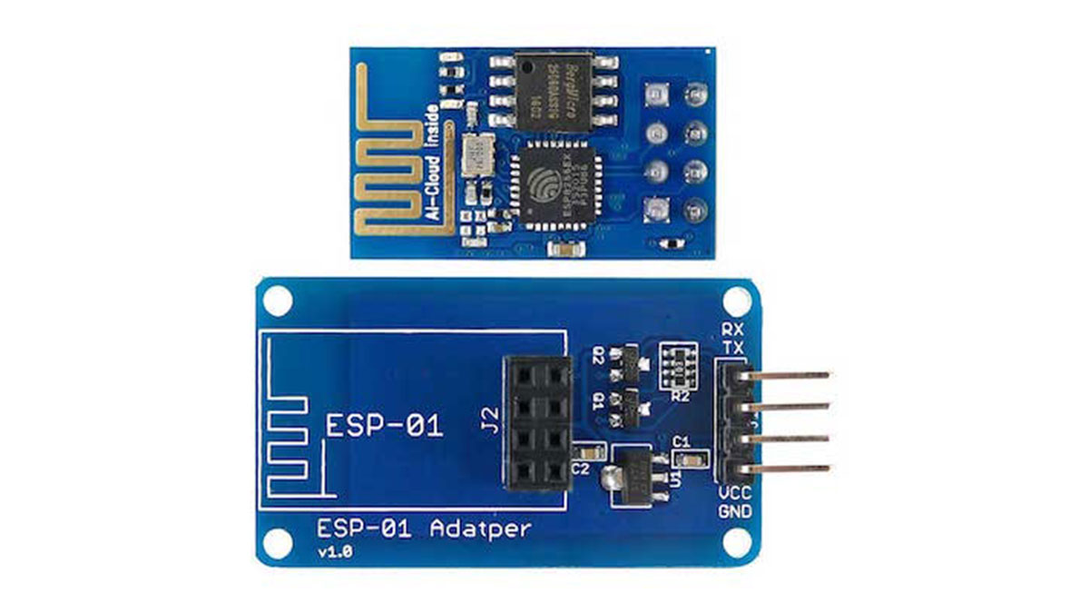
The ESP8266 is a very low-cost module that comes pre-programmed with an AT command set firmware, meaning, you can simply hook this up to your Arduino device and get about as much WiFi-ability as a WiFi Shield offers. This module has a powerful on-board processing and storage capability that allows it to be integrated with the sensors and other application through its GPIOs.
In this tutorial, we can see how to get started with the ESP-01 Wi-Fi module, configure it, and verify that there is communication established between the module and another device without using an FTDI chip.
Bill of Materials
- Arduino board.
- ESP8266.
- Breadboard.
- Female to male and male to male jumpers.
How Does it Work?
The ESP8266 communicates with the Arduino through a serial interface. That is, it uses theArduino’s Rx and Tx pins (digital pins 0 and 1) hooked up to the module for receiving commands and communicates back. The module features a full TCP/UDP stack support and can be configured as a web server.
The ESP8266 or ESP-01 module also has two GPIO pins that can be used for directly manipulating any output devices like LEDs or relays. Moreover, the ESP-01 module powers the onboard ESP8266 through 3.3V. Therefore if your Arduino doesn’t have a 3.3V output pin, you will have to use a voltage regulator like the 78R33 to step down the 5V from the Arduino to 3.3V in order to power the ESP8266.
Setting up the Arduino
First, download Arduino IDE ensure that you have the latest software version (some older versions won’t work). Visit the following URL: https://www.arduino.cc/en/Main/Software.
Upload Bareminimum sketch from examples to your Arduino, this is to make sure that there are no other programs running on the Arduino and using serial communication channel. AT firmware is compatible with the Arduino IDE, so we are going to use this firmware for this tutorial.
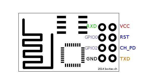
Now, connect the ESP8266 using the instructions below
- VCC will be connected to the 3.3V power supply
- GPIO0 and GPIO2 are general purpose digital ports. GPIO0 also controls the module mode (programming or normal operation). In our case (normal operation), it shall be connected to 3.3V (high). GPIO2 is not used in this example.
- Rx: Goes to Arduino pin0 (But needs a voltage adjusting)
- CH_PD: Chip enable. Keep it on high (3.3V) for normal operation
- RST: Reset. Keep it on high (3.3V) for normal operation. Put it on 0V to reset the chip.
- GND is ground.
- Tx: Goes to Arduino pin1.
Read More: ESP8266 Tutorial: Programming the Onboard GPIO Pins