What would you think about a program, made in the C language of the Arduino IDE, that makes the LoRa radio change frequency? This is what you will learn about in my video today, where you will learn about the differences between LoRa radio, LoRaWAN protocol, and encryption.
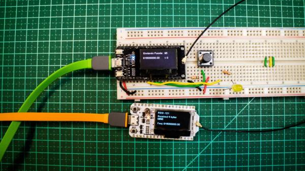
We will then create a project featuring two ESP32 LoRa communicating. Each time we will press a button connected to the SENDER, and the communication frequency will change. This will notify, through the packet to the RECEIVER, to also change the frequency. Thus, this will keep the communication between them.
I already talked about LoRa – from Long Range, that is, Long Distance – in a previous video, and I received some suggestions to talk about the LoRaWAN protocol. LoRa is usually the infrastructure of the radio, while LoRaWAN is the infrastructure of IOT (Internet of Things), where there is a protocol, gateway, and encryption. So today, I’m going to talk about all this, especially the frequency.
Step 1: LoRa® – LoRaWAN ™
In this diagram, we have the figure of the Gateway. When we talk about LoRaWAN, we talk about the protocol that runs on this Gateway and certain devices on the left side of the figure. How much you use this type of protocol is determined based on the infrastructure assembled. So generally, in this case, you pay a monthly fee to the Gateway owner for this potential traffic. In the case of the LoRaWAN protocol, we can use a smartphone as an example, which you enable, hire an operator, and pay for communication. The equipment and infrastructure, therefore, are ready. So now, just program your ESP LoRa so it will reach your goal from this already existing infrastructure. It is important to remember that, in Brazil, we have few Gateways available.
Just so you have an idea of the values of the equipment used in this video, we show the image below. The LoRaWAN Portal development kit is not cheap, and the image uses a Raspberry Pi. If in China, it costs R$2,600, it likely will cost almost double in Brazil due to taxes. In the case of a radio with a SX1301 chip, which operates on eight simultaneous channels, the scenario is the same. This costs R$5,300 in China, and is probably R$10,000 in Brazil.
Step 2: When Should I Use ESP32 Lora?

In the image above, it clearly shows that when you are working with LoRaWAN, you are at the top, at a high level, that is, in the green layer. The radio LoRa is in the orange-colored layer. Here is the difference between these two things in a more visible way. I have not yet been able to make an example using LoRaWAN because, where I live, in the interior of the state of São Paulo, we do not have any such Gateway available. What’s my output? I’ll have to buy one to find out how it works.
Step 3: So, When Should I Use ESP32 Lora?
1. When I need speed “response time”
2. I do not want to pay monthly fees or for traffic
3. There is no public coverage of gateways
4. Specific applications, for example: Remote control
5. Exotic sensors incompatible with standard hardware
* There are probably many more reasons that I just do not remember now.
Step 4: LoRa® – LoRaWAN ™ – and the Frequencies
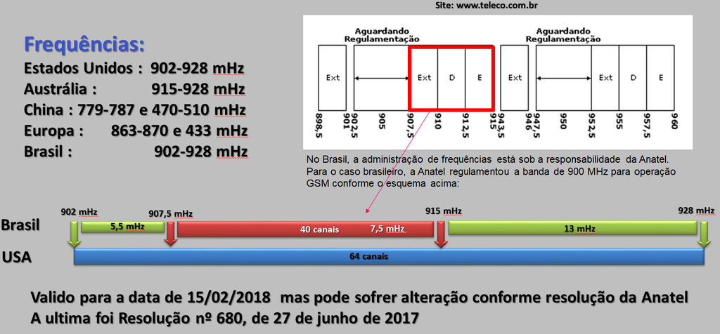
Here is a table that shows how countries have organized themselves in relation to the frequencies of the LoRa network. The LoRa alliance tries to keep the LoRa standard as tight as possible, but that’s not easy. We see that the frequency in the United States is 902 to 928 MHz, a relatively wide band, which allows for 64 channels. Australia already has a slightly narrower band, while there are two tracks in China and Europe.
In Brazil, it should be the same as the US, and a Resolution 680 of Anatel is predicted for the future. However, another resolution under analysis may bring news on this subject. But, again, why is the frequency different than in the United States? In Brazil, frequency management is under the responsibility of Anatel, which has regulated the 900 MHz band for GSM operation. This means that the range between 907.5 to 915 MHz is not available, equivalent to 40 channels, as it belongs to a telephone company. In addition to that, there are 24 channels.
This means that if you are going to install a LoRaWAN Gateway here in Brazil, you will need to configure this Gateway to not use the unavailable frequency range.
Frequencies:
United States: 902-928 mHz
Australia: 915-928 mHz
China: 779-787 and 470-510 mHz
Europe: 863-870 and 433 mHz
Brazil: 902-928 mHz
Step 5: LoRaWan Encryption
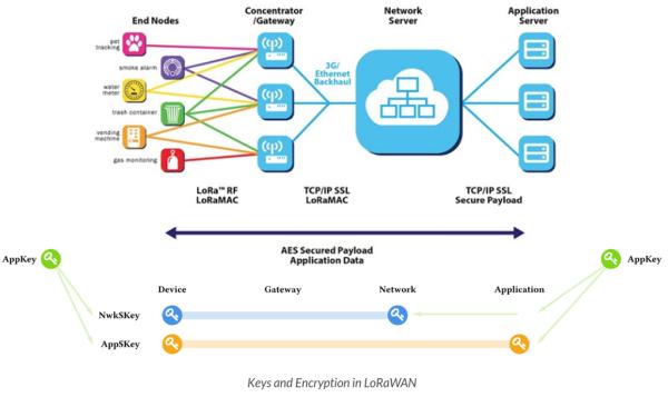
LoRaWAN knows three different 128-bit security keys. The AppKey application key is only known by the device and by the application. When a device joins the network (this is called membership or activation), an AppSKey application session key and a NwkSKey network session key are generated. The NwkSKey is shared with the network, while the AppSKey is kept private. These session keys will be used during the duration of the session.
The figure above shows how these keys are used. AppSKey is used for end-to-end encryption of the frame payload. The algorithm used for this is AES-128, similar to the algorithm used in the 802.15.4 standard. The known NwkSKey is known by the network and by the device, and it is used to validate the integrity of each message through its Message Integrity Code (MIC). This MIC is similar to a checksum except that it prevents the intentional tampering of a message. For this, LoRaWAN uses AES-CMAC.
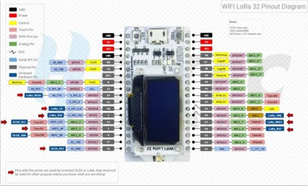
Step 6: Lora Esp32 Oled
Step 7: Assembly
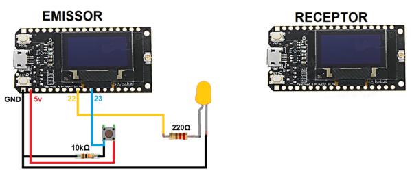
In the assembly, I picked up an ESP from the TTGO, 915 MHz, and another one from the Heltec, 433 MHz. And they both communicated very well. The first frequency is used in Europe, while the second is broadcast more in Brazil and the United States. So, today I’ll show you how you can change the frequency of the LoRa radio. The LoRa radio range is about 15 km away and can be reached within 100 km.
There is a button on the transmitter, and I will explain the diagram here, which makes it easier to assemble. To change, the receiver only needs to be connected to USB for power and the frequency. Both have displays that display the data to be analyzed.
Step 8: Libraries
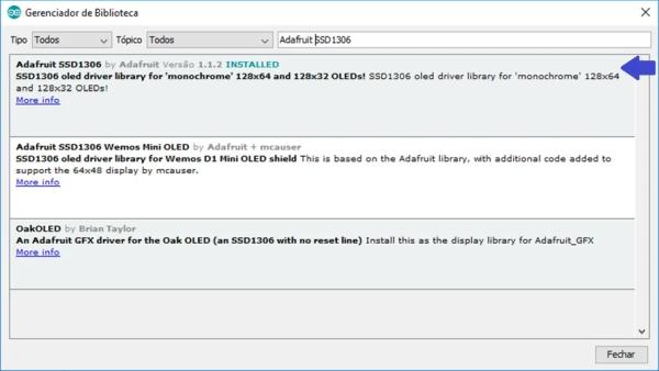
Add the following library “Adafruit SSD1306”, which is from the display that goes in the ESP.
Simply access “Sketch >> Include Libraries >> Manage Libraries…”
Step 9: Software
We will create 2 programs, one for the ESP32 Lora that will work as an SENDER, and another program for the Lora ESP32 that will work as a RECEIVER.
Package: Sender -> Receiver
byte 0: frequency index
byte 1: # delimiter
byte 2: unsigned int
byte 3: unsigned int
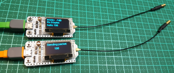
In the video, you can see our assembly. We have both ESPs, one of which has already come as a 915 MHz radio. This radio, then, is already connected and sending packets to the second device. Both start at the frequency of our Array, which has six positions, from 915 to 433 MHz. It is important to remember that the antennas we have in the assembly are 433. Looking at the signal in dB shows -119, as if they were distant from each other, because the antenna is wrong. Our example, however, only serves to show that you can vary greatly the frequency of this LoRa radio. Still, in the video, I give commands to change the frequency.
Step 10: SENDER Program
The SENDER program will be configured to start at the 915Mhz frequency and to send packets. Each time the button connected to it is pressed, the frequency will change and a command will be sent to the RECEIVER to change as well.
SENDER Program Sender
#include <SPI.h>
#include <LoRa.h>
#include (Wire.h>
#include "SSD1306.h"
//pin Button
#define PIN_BTN 23
//pin LED
#define PIN_LED 22
//store the button state
int stateBtn, lastStateBtn;
// Pin definetion of WIFI LoRa 32
// HelTec AutoMation 2017 [email protected]
#define SCK     5    // GPIO5  -- SX127x's SCK
#define MISO    19   // GPIO19 -- SX127x's MISO
#define MOSI    27   // GPIO27 -- SX127x's MOSI
#define SS      18   // GPIO18 -- SX127x's CS
#define RST     14   // GPIO14 -- SX127x's RESET
#define DI00    26   // GPIO26 -- SX127x's IRQ(Interrupt Request)
#define PABOOST true
//array of frequencies valid for the application to change
long int frequencies[6] = {915000000, 915125000, 868000000, 868125000, 433000000, 433125000};
//controls the current frequency index in the array
int indexFreq = 0;
unsigned int counter = 0;
SSD1306 display(0x3c, 4, 15);
Step 11: Setup
LoRa.begin (frequency [index], PABOOST)
Here in Setup, we have a method call. We have the (! Lora.begin (frequency [index], PABOOST)) that initializes the radio at a given frequency, and that frequency is that Array. So, what will the first signal be: 915 MHz. In addition, in this part, I enable the CRC, which is a check digit that you put at the end of the information to know if all the data has arrived correctly at the destination.
void setup() {
pinMode(16,OUTPUT);
  pinMode(2,OUTPUT);
Serial.begin(115200);
  pinMode(PIN_BTN, INPUT);
  pinMode(PIN_LED, OUTPUT);

  digitalWrite(16, LOW);    // set GPIO16 low to reset OLED
  delay(50);
  digitalWrite(16, HIGH); // while OLED is running, must set GPIO16 in high
  display.init();
  display.flipScreenVertically();
  display.setFont(ArialMT_Plain_10);
  delay(1500);
  display.clear();

  SPI.begin(SCK,MISO,MOSI,SS);
  LoRa.setPins(SS,RST,DI00);

  if (!LoRa.begin(frequencies[indexFreq],PABOOST))
  {
    display.drawString(0, 0, "Starting LoRa failed!");
    display.display();
    while (1);
  }
  LoRa.enableCrc();
  display.drawString(0, 0, "LoRa Initial success!");
  display.display();
  delay(1000);
//set button status to LOW stateBtn = lastStateBtn = LOW; digitalWrite(PIN_LED, LOW);
}
Step 12: Loop
In this part, we check and adjust the state of the button. We deal with sending the package, updating the display, and changing the frequency.
void loop()
{
  //get the button status
  stateBtn = digitalRead(PIN_BTN);
  //check if the status of button change to HIGH
  if( (stateBtn != lastStateBtn) && (stateBtn == HIGH) )
  {
    //turns on LED indicating the frequency change
    digitalWrite(PIN_LED, HIGH);
    //check to not overflow the array index
     if( (indexFreq+1) > 5){
        indexFreq = 0;
     }
     else indexFreq++;

     sendPacket();
     refreshDisplay();
     changeFrequency();
  }
  //if button status is LOW, frequency remains the same
  else {
    sendPacket();
    refreshDisplay();
  }

  //increments the counter (is the data to send)
  counter++;
//copies the current state of the button in the state change check variable lastStateBtn = stateBtn;
  //turns on intern LED to indicate the packet has sended
  digitalWrite(2, HIGH);   // turn the LED on (HIGH is the voltage level)
  delay(700);               // wait for a second
  digitalWrite(2, LOW);    // turn the LED off by making the voltage LOW
  delay(500);               // wait for a second
}
changeFrequency and sendPacote
I have a function changefrequency, and in it, we have the (! Lora.begin (frequency [index], PABOOST)). Remember that whenever I start the radio, I have to give an enable in the CRC. We worked again to send the package.
//change the frequency of Lora, the new frequency will be according to the variable "indexFreq" that will pick up in the array the new frequency<br>void changeFrequency()
{
  if (!LoRa.begin(frequencies[indexFreq],PABOOST))
  {
    display.drawString(0, 0, "Starting LoRa failed!");
    display.display();
    while (1);
  }
  LoRa.enableCrc();
  digitalWrite(PIN_LED, LOW); //turns off the frequency change indicator LED
}
//send packet to Lora network
void sendPacket()
{
// send packet
LoRa.beginPacket();
LoRa.print(indexFreq); //current index of the array containing the frequencies
LoRa.print("#"); //delimiter
LoRa.print(counter); //data
LoRa.endPacket();
}updateDisplay
Here, we deal with the display update.
//refresh the informations on display
void refreshDisplay()
{
  display.clear();
  display.setTextAlignment(TEXT_ALIGN_LEFT);
  display.setFont(ArialMT_Plain_10);

  display.drawString(0, 0, "Sending Packet: ");
  display.drawString(90, 0, String(counter));
  display.drawString(0, 20, String(frequencies[indexFreq]));
  display.drawString(90, 20, "I: "+String(indexFreq));
  display.display();
Step 13: RECEPTOR Program
The RECEIVER program will be set to start at the 915Mhz frequency and each packet received will check if the frequency shift command is present to reconfigure.
RECEIVER Program
#include <SPI.h>
#include <LoRa.h>
#include <Wire.h>
#include "SSD1306.h"
// Pin definetion of WIFI LoRa 32
// HelTec AutoMation 2017 [email protected]
#define SCK     5    // GPIO5  -- SX127x's SCK
#define MISO    19   // GPIO19 -- SX127x's MISO
#define MOSI    27   // GPIO27 -- SX127x's MOSI
#define SS      18   // GPIO18 -- SX127x's CS
#define RST     14   // GPIO14 -- SX127x's RESET
#define DI00    26   // GPIO26 -- SX127x's IRQ(Interrupt Request)
#define PABOOST true
SSD1306 display(0x3c, 4, 15);
String rssi = "RSSI --";
String packSize = "--";
String packet ;

//array of frequencies valid for the application to change<br>long int frequencies[6] = {915000000, 915125000, 868000000, 868125000, 433000000, 433125000};
//controls the current frequency index in the array
int indexFreq = 0;Source: ESP32 LoRa Changing Frequency
