Summary of Enhance Home Security with a DIY Arduino Window Alarm Annunciator
This article details an Arduino Uno-based window alarm annunciator system designed for industrial and residential security monitoring. It detects motion or abnormal conditions via sensors, triggering visual LED alerts and audible buzzer warnings. The system includes features for testing, acknowledging alarms to silence sound while keeping lights on, and resetting the status.
Parts used in the Window Alarm Annunciator:
- Arduino Uno microcontroller board
- Seven LEDs (LED1 through LED7)
- Three tactile switches (S1, S2, S3)
- Current-limiting resistors
- Piezo buzzer
- Printed Circuit Board (PCB)
- Enclosure case
- USB connection for power
- elapsedMillis library
This project demonstrates an Arduino Uno-based window alarm annunciator system. Annunciators are commonly employed in industrial settings like manufacturing facilities, power plants, and other process operations to monitor changing plant conditions.
The annunciator alerts operators to any abnormal or deviant parameter readings that require attention. Similarly, such a device can serve as a home security or fire alarm monitoring windows.
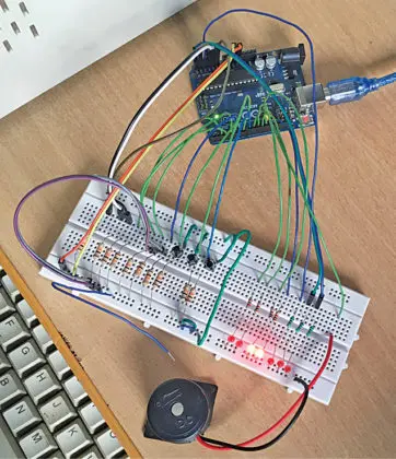
A prototype of the window alarm annunciator is depicted in Figure 1. At the heart of the system is an Arduino Uno microcontroller board which processes sensor input data and triggers alarm notifications.
When motion is detected near a window, the Arduino could activate visual and audible alerts to make security personnel aware. This helps automate monitoring of potentially vulnerable access points.
With the flexibility and programming capabilities of the Arduino platform, simple annunciator designs like this one show promise for diverse monitoring and alarm applications both industrially and residentially.
Circuit and working
The circuit schematic for the window alarm annunciator is provided in Figure 2. At the core is the Arduino Uno microcontroller board (labeled as board1) which coordinates the various components.
There are seven LEDs (LED1 through LED7) connected to digital pins on the Arduino to serve as visual indicators. Three tactile switches (S1 through S3) wired to other pins allow for user input/control.
Additional discrete passive elements like resistors are incorporated as needed. For example, current-limiting resistors enable the LEDs to safely illuminate under digital control from the Arduino pins.
Taken together, the Arduino along with the LEDs, switches and basic supporting parts comprise the full circuit design. By following this schematic, the annunciator prototype’s functionality can be replicated through the programmed interactions of its electronic subsystems.
The Arduino board integrates it all through embedded code, responding to switch presses and toggling LED patterns based on simulated sensor readings or alarm conditions.
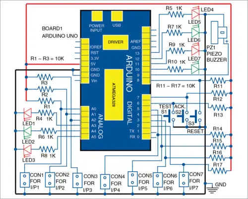
This alarm system employs seven input connections, labeled CON1 through CON7, to trigger alarms through normally-open (NO) contacts. Additionally, three input switches (S1 through S3) are provided for testing, acknowledging, and resetting the alarm. Out of eight outputs, seven are connected to LEDs corresponding to the seven input alarm contacts, while the eighth output is dedicated to a buzzer. (A hooter can be substituted for the buzzer with additional circuitry.)
All alarm inputs are designed for NO contacts. In addition to digital pins 2 through 13 on the Arduino, analog pins A0 through A5 are also utilized as digital I/O pins to monitor the seven different input conditions.
Upon the closure of any input alarm contact, the corresponding output LED will blink rapidly, and the piezo buzzer will activate to draw attention to nearby users. Pressing the acknowledge pushbutton switch (S2) silences the alarm. With the acknowledge button pressed and the input alarm contact still closed, the LED will blink at a slower rate. In other words, if the alarm input contact is opened, the alarm sound will cease, but the LED will continue to flash at a reduced rate. Pressing the reset button (S3) completely extinguishes the LED.
Let’s consider an example. Initially, all inputs are open, and all LEDs are off. If a problem arises with the first machine, the first input I/P1 at CON1 will close, causing LED1 to flash rapidly and PZ1 to emit an alarm sound. With I/P1 closed and S2 pressed, PZ1 will deactivate, but LED1 will remain illuminated. When S2 is pressed with I/P1 open, PZ1 will remain off, and LED1 will blink slowly until S3 is momentarily pressed.
The test pushbutton switch S1 is provided to verify the LEDs and buzzer functionality. Pressing S1 will cause all window alarm LEDs to glow steadily and activate the buzzer. This will continue until S1 is released.
Software
The annunciator code is written as an Arduino sketch (Annunciator.ino) using the Arduino programming language within the Arduino IDE version 1.8.5 environment.
Before compiling and uploading this program to the Arduino Uno, first check that the elapsedMillis library function is present in the IDE. This can be done by navigating to Sketch > Include Libraries.
If the elapsedMillis function is not already listed, it needs to be installed. Download the zip file containing the elapsedMillis library from the specified source.efymag.com URL.
Next, add this .zip library file to the IDE using the steps Sketch > Include Libraries > Add .ZIP Library. Browse and select the downloaded elapsedMillis zip.
This will incorporate the necessary function into the library listings. Verify it now shows up in the libraries menu.
Only then is the Annunciator sketch code ready to be loaded onto the Arduino board using the usual upload procedure from the IDE interface. The elapsedMillis calls will now be properly resolved during programming.
Construction and testing
The printed circuit board (PCB) design for the annunciator is depicted in Figures 3 and 4. Figure 3 shows the circuit board layout, outlining how the different components connect via the copper traces.
Figure 4 then provides a view of the component placement guide, specifying where each discrete part is soldered onto the PCB. After assembling according to these graphical designs, enclose the fully built circuit inside an appropriate enclosure case.
Mount all the LED indicators flush onto one side of the enclosure cabinet for easy viewing. Similarly, fasten the piezo buzzer to the opposite side so its audible alerts are directed outward.
Power for the system is derived directly from the USB connection to the Arduino board, avoiding the need for an extra power supply module. Simply plug the Arduino into the laptop or PC over USB to energize the entire annunciator device.
Following these assembly and enclosure instructions allows replication of a working prototype based on the described Arduino-driven window alarm annunciator design.
- What is the primary function of this project?
The system monitors changing plant conditions or home security windows by alerting operators to abnormal readings using visual and audible signals. - How does the system indicate a rapid alarm condition?
When an input alarm contact closes, the corresponding output LED blinks rapidly and the piezo buzzer activates. - Can the elapsedMillis library be installed manually?
Yes, users must download the zip file from the specified source and add it via Sketch > Include Libraries > Add .ZIP Library. - What happens when the acknowledge switch S2 is pressed?
Pressing S2 silences the alarm sound, but if the input contact remains closed, the LED continues to blink at a slower rate. - How is the test pushbutton switch S1 utilized?
Pressing S1 causes all window alarm LEDs to glow steadily and activates the buzzer to verify functionality until released. - What type of contacts are used for the alarm inputs?
All alarm inputs are designed for normally-open contacts that trigger alarms upon closure. - Where is power derived from for the system?
Power is derived directly from the USB connection to the Arduino board, eliminating the need for an extra power supply module. - Which pins on the Arduino are used for the seven inputs?
The system utilizes digital pins 2 through 13 and analog pins A0 through A5 as digital I/O pins to monitor the seven different input conditions. - How can the eighth output be substituted?
The eighth output dedicated to the buzzer can be substituted with a hooter, though additional circuitry is required. - What software environment is required to compile the code?
The code is written using the Arduino programming language within the Arduino IDE version 1.8.5 environment.